
Wireless charger for electronic device

a charger and electronic device technology, applied in the field of electronic devices, can solve the problems of increasing the level of spurious electromagnetic radiation, complicating the uniform energy transfer, and difficulty in the application of prior-art wireless technology of electric power transfer

Active Publication Date: 2014-12-25
SAMSUNG ELECTRONICS CO LTD
View PDF6 Cites 273 Cited by
  • Summary
  • Abstract
  • Description
  • Claims
  • Application Information

AI Technical Summary

Benefits of technology

The present invention is a wireless charger for various mobile devices that reduces interference and spurious signals in the surrounding environment. Furthermore, the charger is designed to be positioned randomly without affecting the charging process. The technical effects of this invention include improved efficiency, stability, and reliability of wireless charging for various mobile devices.

Problems solved by technology

The increasing of the dimension of the transmitting coils increases the level of spurious electromagnetic radiation and complicates providing of uniform efficiency of a transfer of energy by a surface of a charger.
This causes difficulty in the application of prior-art wireless technologies of transfer of the electric power for charging of electronic devices such as mobile devices and other household appliances.

Method used


Image

  • Wireless charger for electronic device
  • Wireless charger for electronic device
  • Wireless charger for electronic device

Examples


Embodiment Construction

[0018]Hereinafter, various embodiments of the present invention will be described in detail with reference to the accompanying drawings. In the following description, when it is determined that a detailed description of related known functions or structures causes confusion in the subject matter of the present invention, the description thereof will be omitted. In addition, terms described below are defined in consideration of functions in the embodiment, but they may be replaced with other terms according to intention of a user or an operator, or a practice. Therefore, the terms will be defined more definitely through the description of the various embodiments of the present invention. Further, use of an ordinal number such as first and second is to distinguish objects having identical names from one another, and an order of the objects may be determined arbitrarily.

[0019]In an embodiment of the present invention, the system includes a first part which is the charger. It includes a...


PUM


Abstract

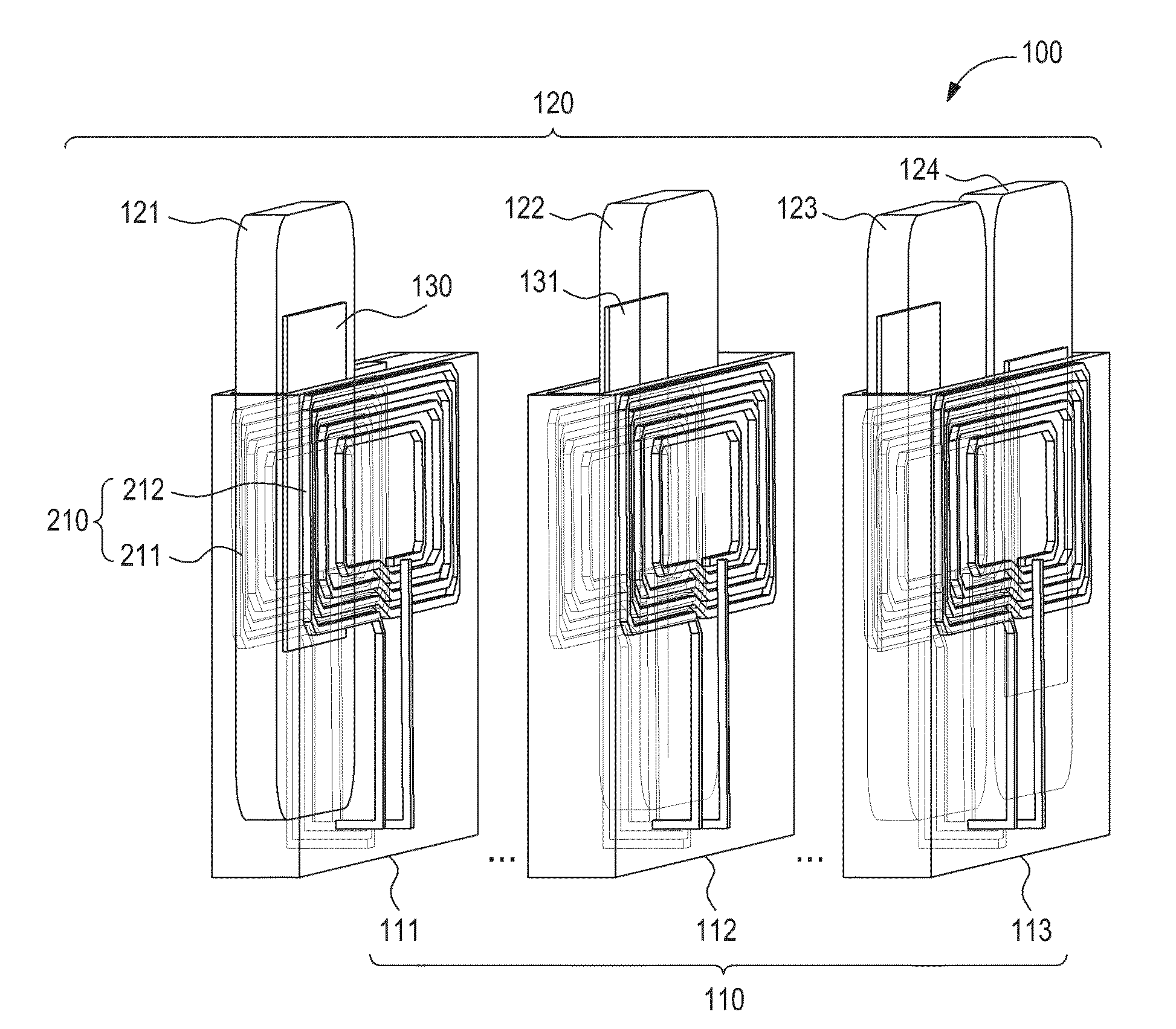
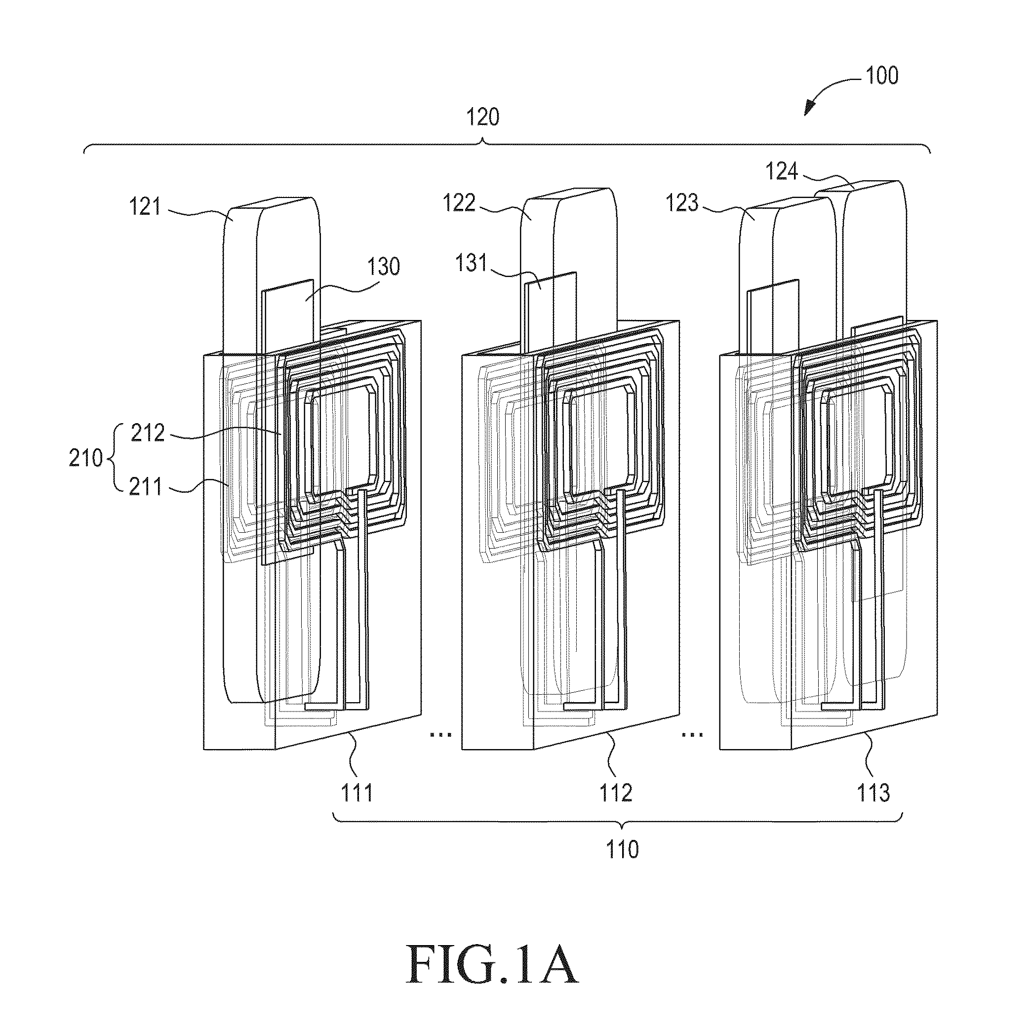
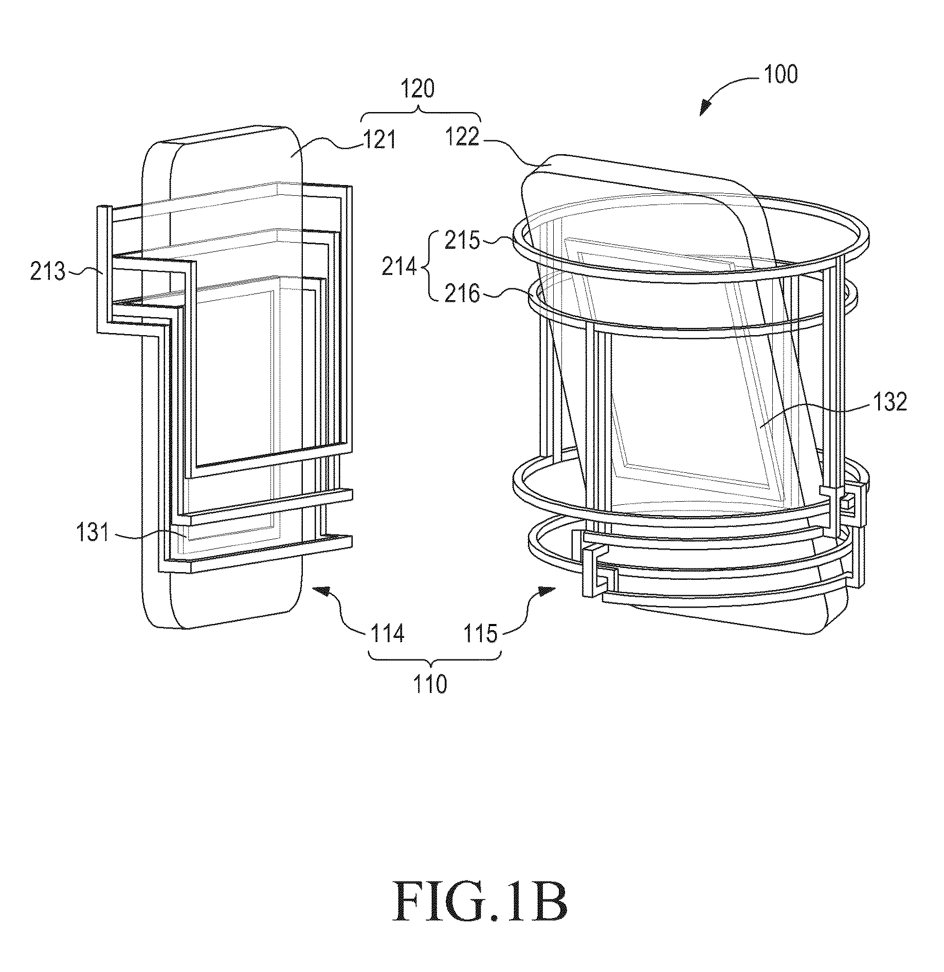
A wireless charger for an electronic device is provided, which includes one or more charge cells formed by one or more structures of transmitting inductance coils, each of the charge cells receiving an electronic device, and an electric power supply circuit of transmitting coils. The transmitting coils surround the charge cells on at least two sides, respectively, and generate a uniformly distributed magnetic field such that the magnetic fields, generated by currents in parts of the structure of the transmitting coils, are mutually subtracted out of the charge cells and summarized inside the charge cell in an area in which the electronic device for reception of energy is located.

Description

PRIORITY[0001]The present application claims priority under 35 U.S.C. §119(a) to Korean Patent Application Serial No. 10-2013-0135556, filed on Nov. 8, 2013 in the Korean Intellectual Property Office, and Russian Federation Patent Application Serial No. 2013127771, filed on Jun. 19, 2013 in Russian Federation Patent Office, the entire disclosures of each of which are incorporated herein by reference.BACKGROUND[0002]1. Field of the Invention[0003]The present invention generally relates to electronic devices including mobile devices, and more particularly, to wireless charger and devices for wireless energy transfer, for example, to an electronic device.[0004]2. Description of the Related Art[0005]Systems for transfer of electromagnetic energy may be classified into radiating and non-radiating systems. Radiating systems for transfer of energy are based on narrow-band transmitters and use electromagnetic radiation in a far-field region. Non-radiating systems for a transfer of energy ar...

Claims


Application Information

Patent Timeline
IPC IPC(8): H02J7/02
CPCH02J7/025H02J7/0044H02J7/0013H02J50/90H02J50/12H02J50/40H02J50/70H02J7/0042H03H7/38H02J2310/22H02J50/10
Inventor ARKHIPENKOV, VLADIMIR YAKOVLEVICHKHRIPKOV, ALEXANDR NILOLAEVICHKIM, JOON-LLPAVLOV, KONSTANTIN ALEKSANDROVICHMAKURIN, MIKHAIL NIKOLAEVICHOLYUNIN, NIKOLAY NIKOLAEVICH
Owner SAMSUNG ELECTRONICS CO LTD
Learn More