
Cooling Module

Active Publication Date: 2014-12-11
BAYERISCHE MOTOREN WERKE AG
View PDF1 Cites 2 Cited by
  • Summary
  • Abstract
  • Description
  • Claims
  • Application Information

AI Technical Summary

Benefits of technology

[0009]According to the invention, it is therefore provided that at least the second heat exchanger is designed such that, before final assembly, its block-type heat exchanger networks/-partial networks, can be through-coated in smaller or thinner units. This can be implemented by a block-type construction of the heat exchanger matrix which, after assembly, then resembles the final system depth. As a result, the objective of maximally possible NMOG credits can be achieved in the manner of emission credits. The reaching of the objective

Problems solved by technology

Because of the larger overall depth, for example, of a charge air cooler, a functionally effective through-coating by means of a PremAir

Method used


Image

  • Cooling Module
  • Cooling Module

Examples


Example

DETAILED DESCRIPTION OF THE DRAWINGS

[0020]In the following, the same reference numbers will be used for identical components in both drawings.

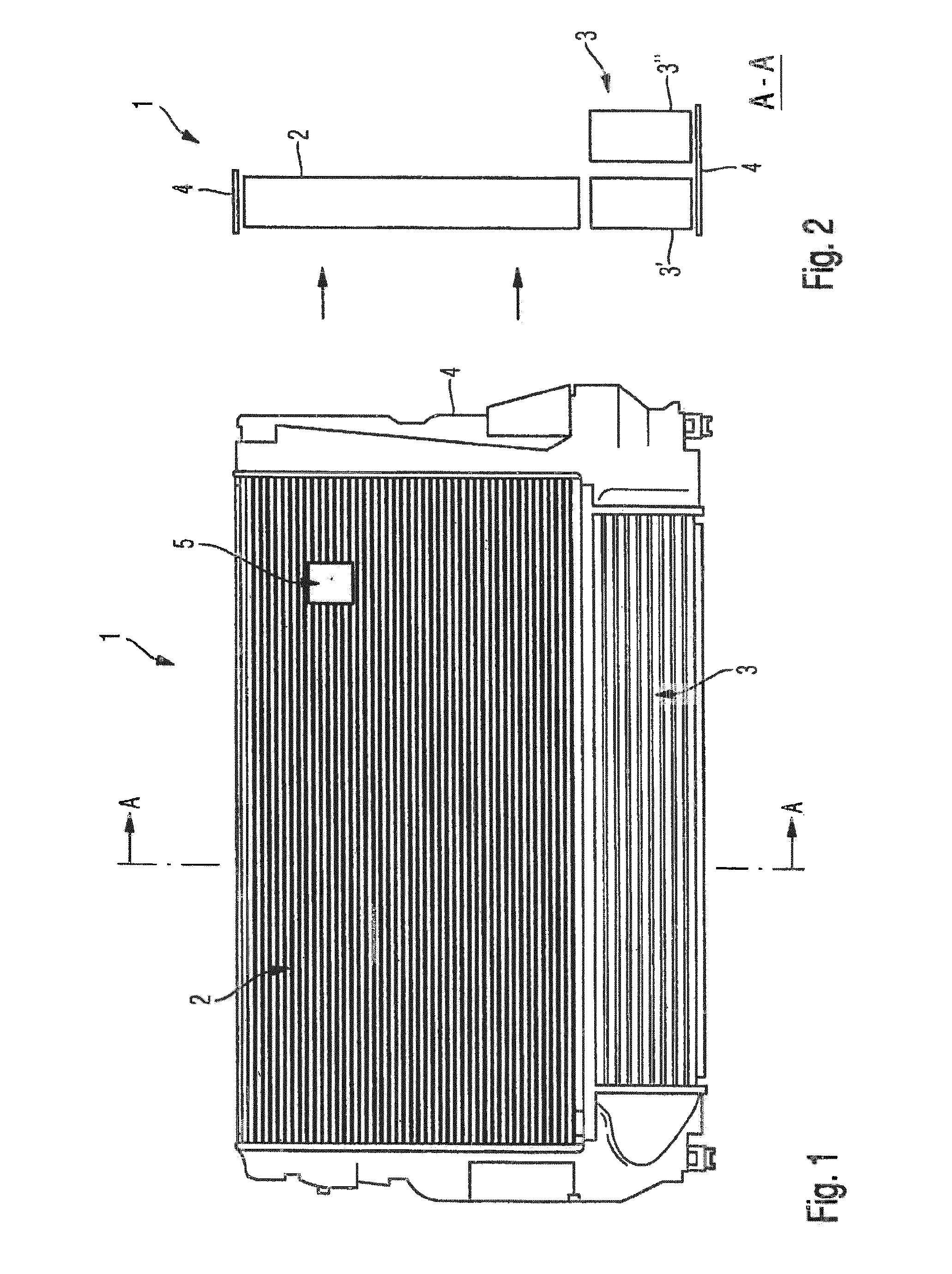
[0021]FIG. 1 is a front view of a cooling module according to an embodiment of the invention. The cooling module 1 is composed of at least a first and a second heat exchanger 2, 3, which are connected in a common frame 4 or directly with one another by way of the fluid boxes. In a known manner, cooling air can flow through both heat exchangers 2, 3. The second heat exchanger 3 has a greater structural depth than the first heat exchanger 2 in the flow direction of the cooling air.

[0022]The cooling module 1 is characterized in that the first and the second heat exchanger 2, 3 have a catalytic coating, and the second heat exchanger 3 is composed of at least one first and one second partial heat exchanger 3′, 3″ according to FIG. 2, which are arranged one behind the other in the flow direction of the cooling air and which are operatively connected...


PUM

PropertyMeasurementUnit
Timeaaaaaaaaaa
Temperatureaaaaaaaaaa
Flow rateaaaaaaaaaa

Abstract

A cooling module, composed of at least one first and one second heat exchanger, are connected in a common frame or directly to one another, it being possible for cooling air to flow through both heat exchangers. The second heat exchanger has a greater structural depth than the first heat exchanger in the flow direction of the cooling air. The first heat exchanger and the second heat exchanger have a catalytic coating and the second heat exchanger is composed of at least one first and one second partial heat exchanger which are arranged one behind the other in the flow direction of the cooling air and which are operatively connected to one another. By means of the configuration according to the invention, the largest possible catalytically active coating surface area is attained.

Description

CROSS REFERENCE TO RELATED APPLICATIONS[0001]This application is a continuation of PCT International Application No. PCT / EP2013 / 051671, filed Jan. 29, 2013, which claims priority under 35 U.S.C. §119 from German Patent Application No. 10 2012 203 608.3, filed Jul. 3, 2012, the entire disclosures of which are herein expressly incorporated by reference.BACKGROUND AND SUMMARY OF THE INVENTION[0002]The invention relates to a cooling module composed of at least a first and a second heat exchanger, which are connected in a common frame or directly with one another, and wherein cooling air can flow through both heat exchangers. The second heat exchanger has a greater structural depth than the first heat exchanger in the flow direction of the cooling air.[0003]A cooling module of the above-mentioned type is known, for example, from German Published Patent Application DE 10 2010 011 495 A1. From this document, on which the present invention is based, a cooling module for motor vehicles is kn...

Claims


Application Information

Patent Timeline
IPC IPC(8): F01P3/18F02B29/04F02M25/07F28F21/00
CPCF01P3/18F28F21/00F01P2003/187F02M25/0737F02B29/0462B01D53/8675B01D2259/4558F01P2003/182B01D53/88B01D2259/4566F02M26/32F02B29/0475F02B29/0443F02B29/0493Y02T10/12F01P2060/02
Inventor STUMPF, STEPHAN
Owner BAYERISCHE MOTOREN WERKE AG
Learn More