
Method for controlling a device for changing the spreading ring sector of a disc spreader and disc spreader designed to carry out such a method

a technology of disc spreader and spreading ring, which is applied in the direction of centrifugal wheel fertiliser, liquid spraying apparatus, fertilising methods, etc., can solve the problems of inability to detect the transverse distribution of granular material, inability to bring about uniform granular material distribution, and considerable inaccuracy when detecting the actual sta

Active Publication Date: 2014-09-18
RAUCH LANDMASCHFAB
View PDF4 Cites 9 Cited by
  • Summary
  • Abstract
  • Description
  • Claims
  • Application Information

AI Technical Summary

Benefits of technology

The invention is a method for controlling a device that changes the spreading ring sector of a disc spreader. The method uses sensors to detect actual values of various parameters that affect the spreading of granular materials. Based on these values, the device can be adjusted to achieve a more accurate and representative setting that ensures the desired distribution of materials on the ground.

Problems solved by technology

In contrast, in other applications such as, in particular, in the case of winter service spreaders it is attempted to achieve a spreading pattern which has edges which are as steep as possible since an overlap method is not possible here.
However, even this often does not bring about a uniform transverse distribution of the granular material because the distribution is influenced by further factors during the spreading operation (subsequently), for example the inclination situation of the spreader on uneven ground, by influences of the wind, the exposure of the granular material to air humidity or even rain, by possible changes, mentioned above, in the physical properties of the granular material etc.
However, in this way it is not possible to detect the transverse distribution of the granular material over the entire ejection range and this method ignores, in particular, the fact that the maximum quantity does not necessarily have to be located in the centre of the spreading sector.
Consequently, overall considerable inaccuracies occur when detecting the actual state by sensor.
As a result, although definitive information is obtained about the quantity of granular material discharged, such definitive information is not obtained about the quantity distribution in the spreading ring sector.
Moreover, the detection of the weight is structurally very complex and also inaccurate on uneven ground because of the dynamic operation of the disc spreader.
However, in fact only the ejection range at the disc and not the spreading ring sector is also determined here and the sensory detection of the granular material is subject to considerable inaccuracies.
In this method, on the one hand measurement is carried out at a location in the ejection range which is not detected, on the other hand, the relationships between the measured values and the settings which are performed subsequently cannot be understood on the basis of the document.
However, with such a disc spreader which is embodied in such a way it has also been found that the setting parameters of the device for changing the spreading ring sector, generated on the basis of the actual values, detected by sensor, for the respective throwing parameters are subject to considerable inaccuracies which result in correspondingly inaccurate setting of the device for changing the spreading ring sector of the disc spreader, which results in a transverse distribution of the granular material (over the working width) which is not optimum.

Method used


Image

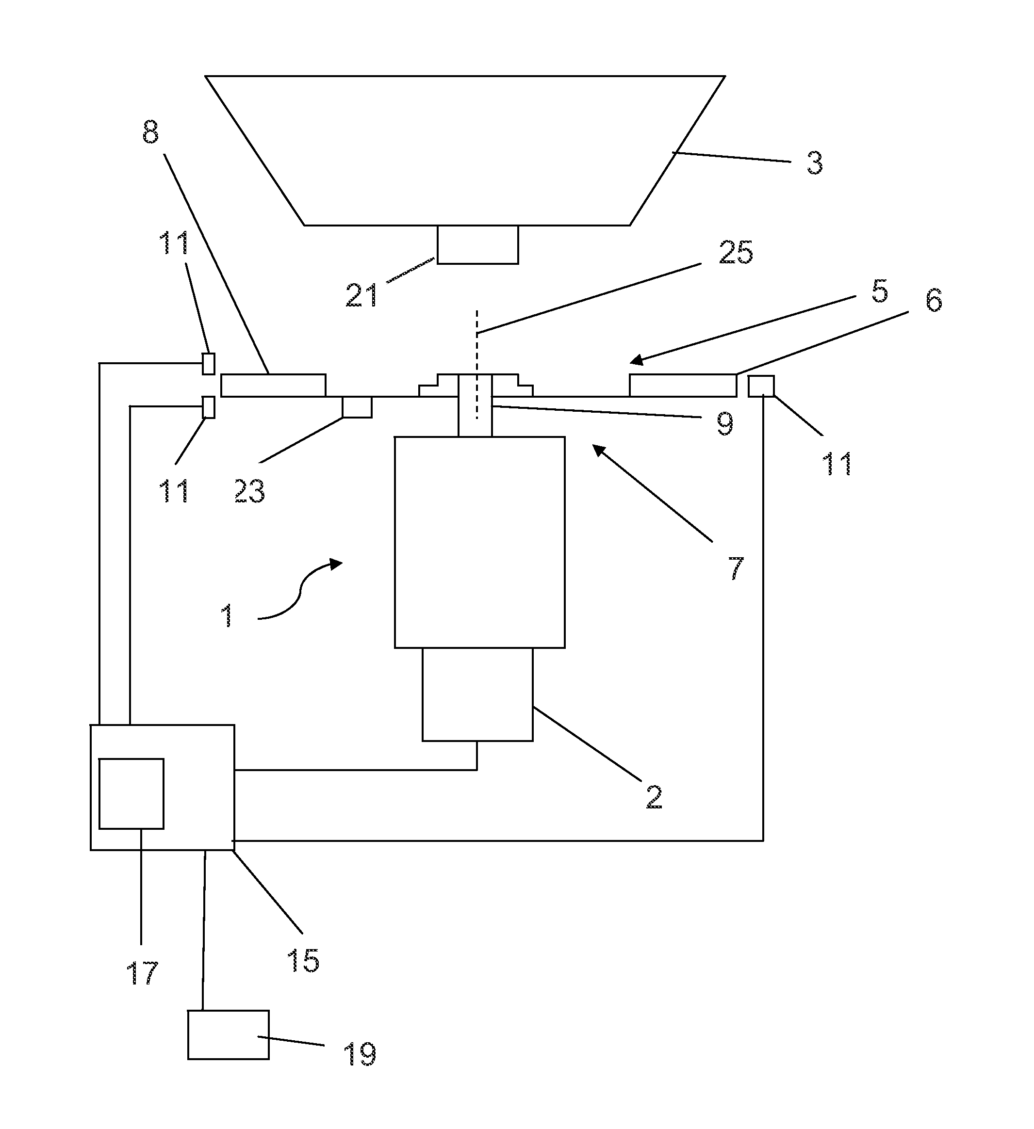
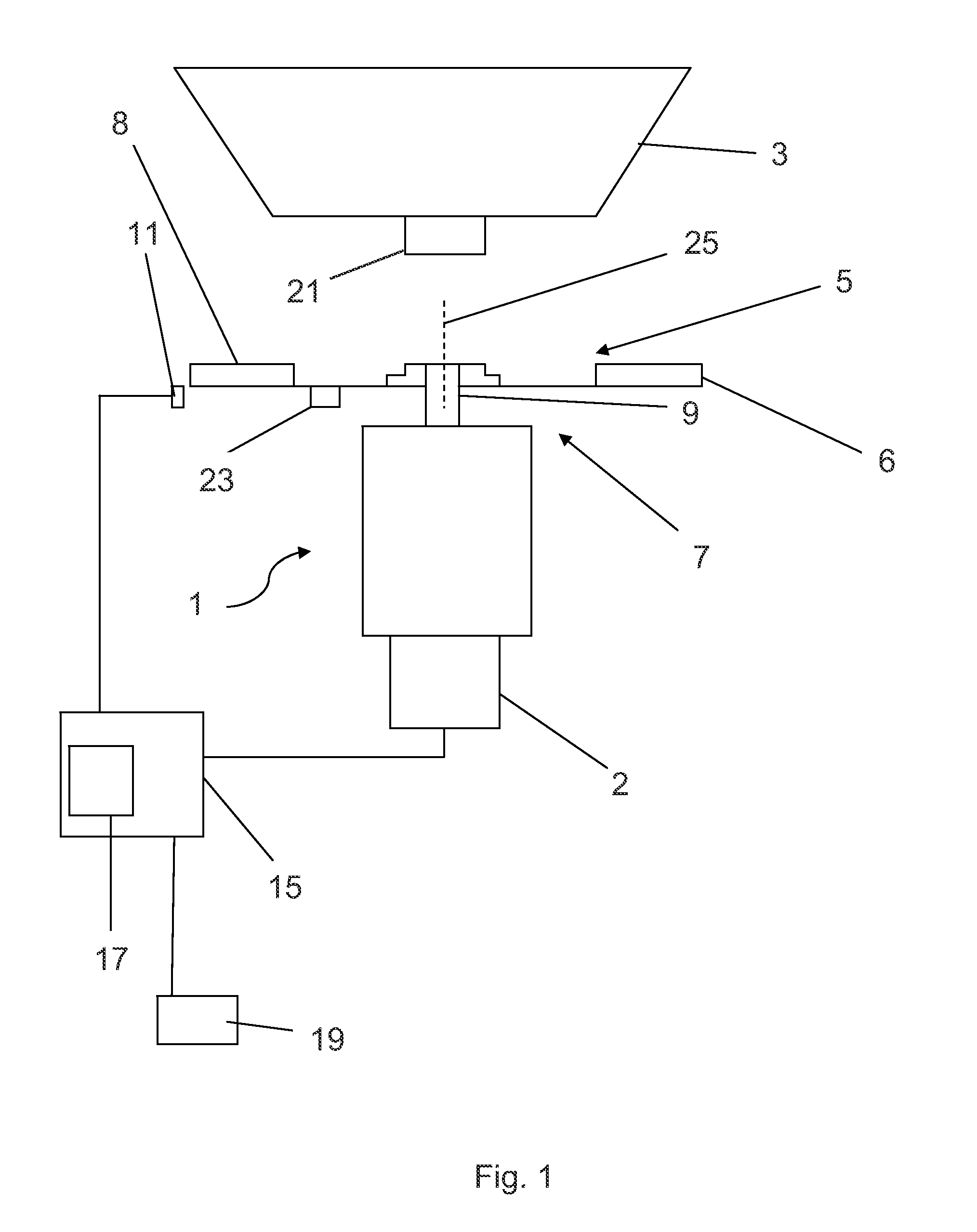
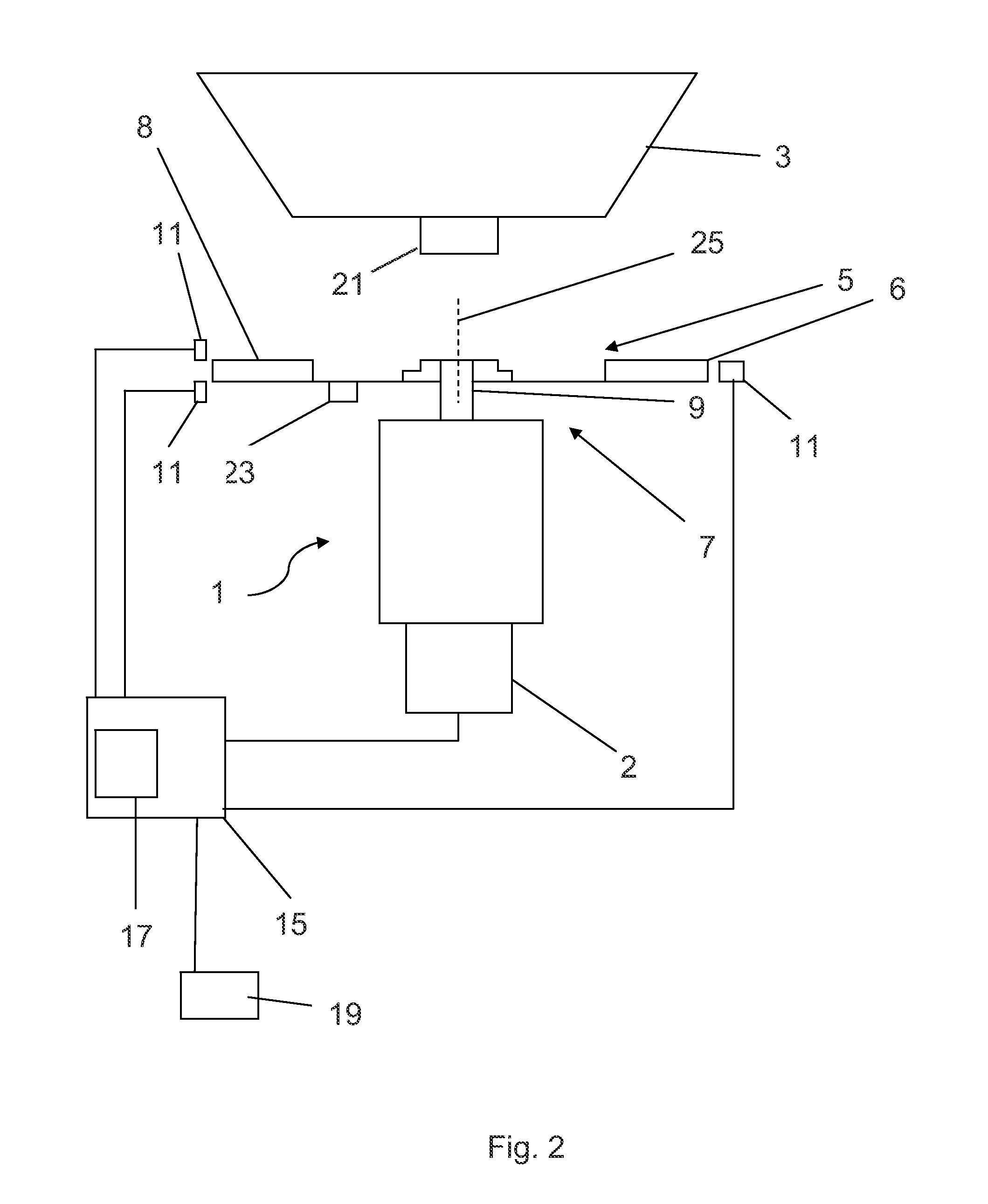
  • Method for controlling a device for changing the spreading ring sector of a disc spreader and disc spreader designed to carry out such a method
  • Method for controlling a device for changing the spreading ring sector of a disc spreader and disc spreader designed to carry out such a method
  • Method for controlling a device for changing the spreading ring sector of a disc spreader and disc spreader designed to carry out such a method

Examples


Embodiment Construction

[0036]The invention is based on the realization that the sensors which are respectively used for detecting one or more throwing parameters are always capable of detecting only a number of values which are representative of the throwing parameters, whereas the type of the respectively used distributor disc or the combination of distributor disc / thrower blades brings about a change in virtually all the throwing parameters. Consequently, the use of another distributor disc and / or of other thrower blades inevitably leads to faulty setting parameters if only a number of throwing parameters are detected by sensor and a setting parameter is derived therefrom, without taking into account the fact that other throwing parameters, not detected by sensor and which basically required a setting parameter which was different from the latter, have also changed as a result.

[0037]In this context, the replacement of one distributor disc with another with a larger circumference in comparison is mention...


PUM


Abstract

Method for controlling a device for changing the spreading ring sector of a disc spreader including a controllable metering device, a distributor disc arranged underneath the metering device and provided with thrower blades, and the device for changing the spreading ring sector of the granular material on the ground. Functional dependencies of a setting parameter of the device for changing the spreading ring sector on a throwing parameter are stored in a database of a control unit assigned to the device for adjusting the spreading ring sector, and a set point value of the throwing parameter or of the setting parameter corresponding thereto is input in the control unit. An actual value of the throwing parameter is determined using a sensor, arranged near to the circumference of the distributor disc, and the actual value of the throwing parameter is compared with the set point value thereof in the control unit.

Description

CROSS REFERENCE TO RELATED APPLICATIONS[0001]This application claims the benefit of priority under 35 U.S.C. §119 of German patent application DE 10 2013 004 195.3 filed Mar. 12, 2013, the entire contents of which are incorporated herein by reference.FIELD OF THE INVENTION[0002]The invention relates to a method for controlling at least one device for changing the spreading ring sector of a disc spreader which comprises at least one controllable metering device, at least one distributor disc which is arranged underneath the metering device and is provided with thrower blades, and the at least one device for changing the spreading ring sector of the granular material on the ground, wherein:[0003](a) functional dependencies of at least one setting parameter of the device for changing the spreading ring sector on at least one throwing parameter are stored in a database of a control unit which is assigned to the device for adjusting the spreading ring sector;[0004](b) a set point value o...

Claims


Application Information

Patent Timeline
IPC IPC(8): A01C21/00E01H10/00
CPCE01H10/007A01C21/002A01C17/008A01C21/00
Inventor STÖCKLIN, VOLKERTHULLNER, CHRISTIANMINARDI, MARTINORAUCH, NORBERT
Owner RAUCH LANDMASCHFAB
Learn More