
Dual Pressure Sensor Patient Ventilator

a patient ventilator and pressure sensor technology, applied in the field of patient ventilation systems, can solve the problems of patient difficulty in breathing deeply enough, respiratory path usually extremely slack and tend to collapse, and constant overload or exhaustion of the respiratory pump

Inactive Publication Date: 2014-09-18
BREATHE TECHNOLOGIES INC
View PDF25 Cites 21 Cited by
  • Summary
  • Abstract
  • Description
  • Claims
  • Application Information

AI Technical Summary

Benefits of technology

The present patent is about a ventilation apparatus that delivers pressurized oxygen enriched gas to a patient interface through a gas delivery conduit. The apparatus has a valve and two pressure sensors to detect the patient's inspiratory and expiratory phases. The controller regulates the valve to deliver the gas to the patient interface during the patient's inspiratory phase and expiratory phase. The technical effect of this patent is to provide a ventilation system that can deliver targeted oxygen enriched gas to patients during respiratory phases, improving respiratory function and patient outcomes.

Problems solved by technology

With patients suffering from certain diseases or other serious medical conditions, there is a constant overload on or exhaustion of the respiratory pump.
A typical syndrome is pulmonary emphysema with flat-standing diaphragms without the ability to contract, and the respiratory paths are usually extremely slack and tend to collapse.
Consequentially, the patient experiences difficulty with breathing deeply enough and providing the body with needed oxygen while also expelling waste carbon dioxide.
However, the vast majority of contemporary ventilators instead use positive pressure to deliver gas to the patient's lungs via a patient circuit between the ventilator and the patient.
However, to the extent the patient is capable of spontaneous respiration, any positive or negative pressure applied by the ventilator in opposition thereto may cause discomfort.

Method used


Image

  • Dual Pressure Sensor Patient Ventilator
  • Dual Pressure Sensor Patient Ventilator
  • Dual Pressure Sensor Patient Ventilator

Examples


Embodiment Construction

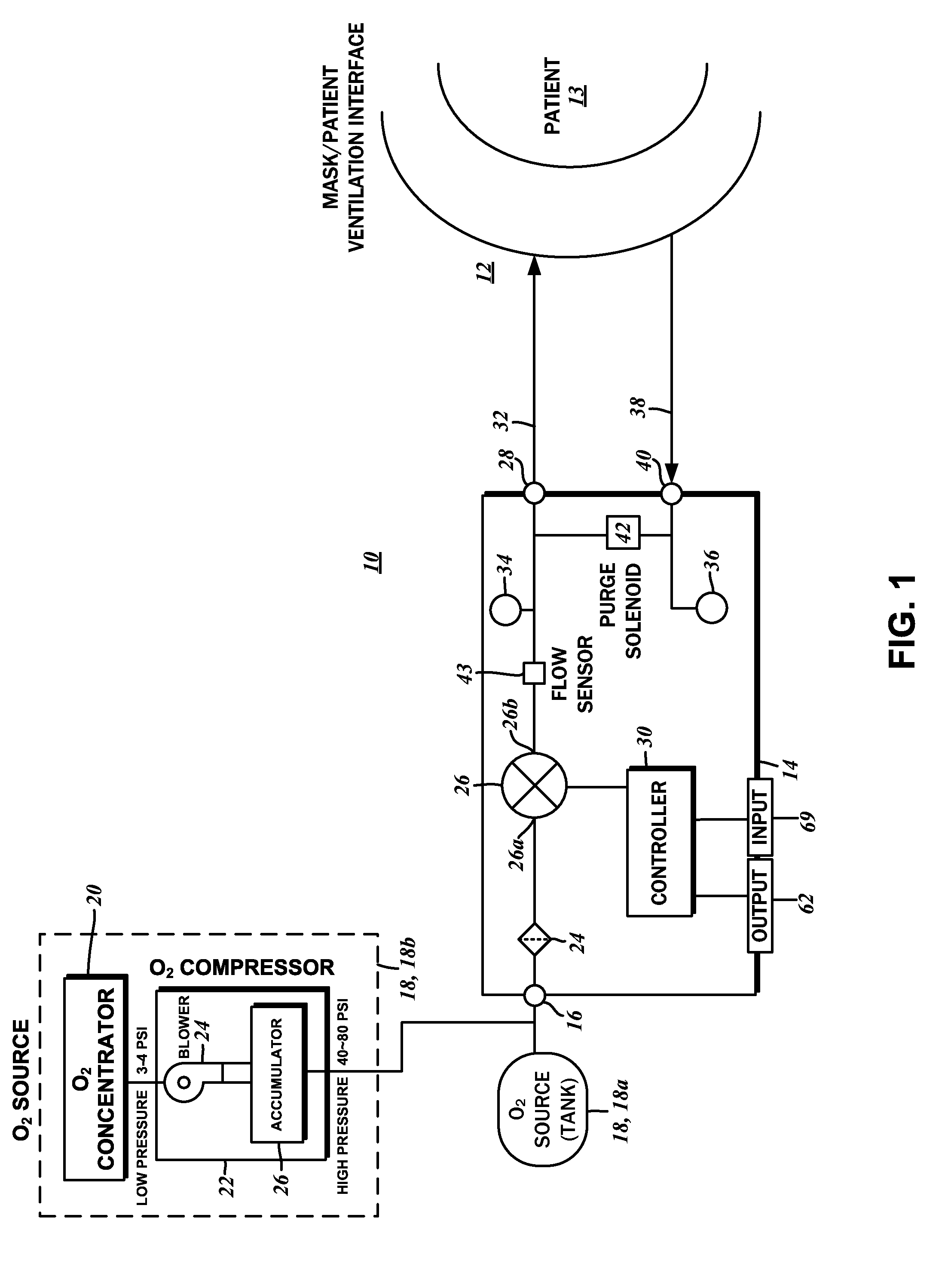
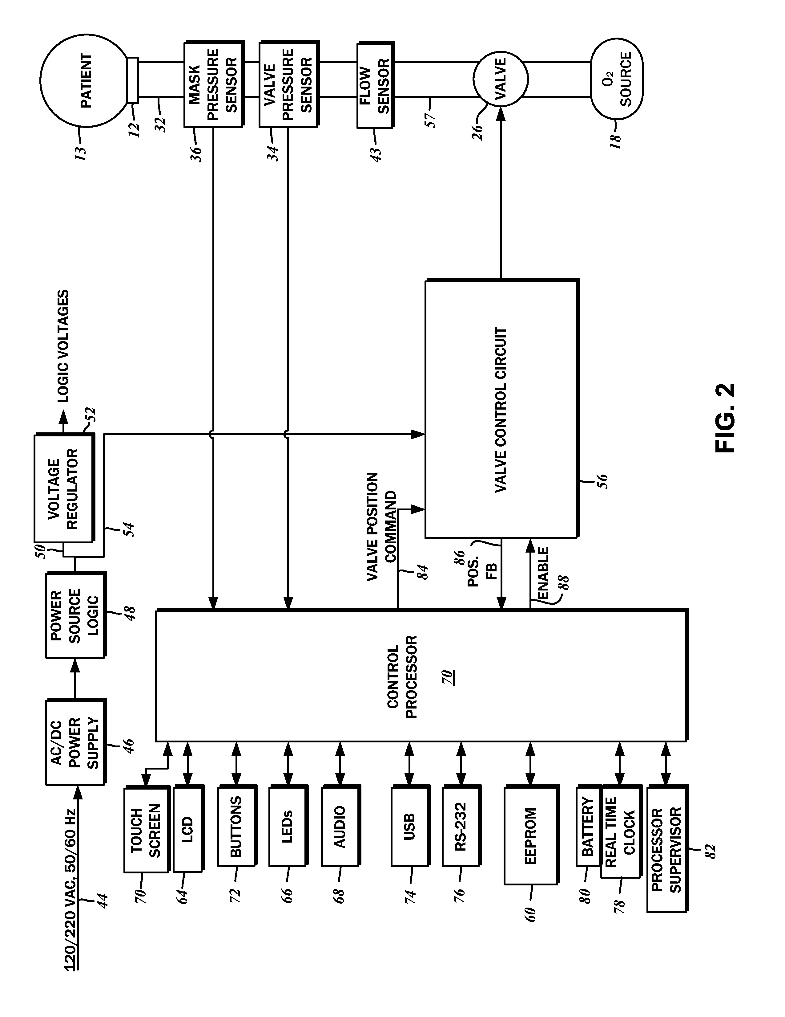
[0026]The detailed description set forth below in connection with the appended drawings is intended as a description of the several presently contemplated embodiments of a system for continuous patient ventilation. The system delivers breathing gas to a patient for respiratory assistance and implements various methods for the selective pressure augmentation throughout the breathing cycle. This description is not intended to represent the only form in which the disclosed invention may be developed or utilized. The description sets forth the functions and features in connection with the illustrated embodiments. It is to be understood, however, that the same or equivalent functions may be accomplished by different embodiments that are also intended to be encompassed within the scope of the present disclosure. It is further understood that the use of relational terms such as first and second and the like are used solely to distinguish one from another entity without necessarily requirin...


PUM


Abstract

A patient ventilation apparatus is disclosed. The apparatus includes an inlet port connectible to an oxygen source with pressurized oxygen enriched gas. An outlet port is connectible over a gas delivery conduit to a patient interface configured for fitment on a patient respiratory passageway. A valve is in pneumatic communication with the inlet port and with the outlet port. A first pressure sensor measures a patient interface pressure, which is connectible to the first pressure sensor over a pressure sensor line. A second pressure sensor measures a valve output pressure. A controller is in communication with the first pressure sensor, the second pressure sensor, and the flow sensor, to detect a patient inspiratory phase and a patient expiratory phase based upon a combination of measurements of the first pressure sensor and the second pressure sensor and to regulate the valve to selectively deliver pressurized oxygen enriched gas to the patient interface.

Description

CROSS-REFERENCE TO RELATED APPLICATIONS[0001]Not ApplicableSTATEMENT RE: FEDERALLY SPONSORED RESEARCH / DEVELOPMENT[0002]Not ApplicableBACKGROUND[0003]1. Field of the Invention[0004]The present disclosure relates generally to the patient ventilation systems, and more particularly, to methods and systems for non-invasive ventilation in which a pressurized flow of breathable gas is provided to a patient utilizing dual pressure sensors at a source and at a ventilation mask.[0005]2. Description of the Related Art[0006]The respiration system of the human body provides needed oxygen intake, oxygen / carbon dioxide exchange, and carbon dioxide expulsion functions, each of which involves the lungs. In this regard, the lungs function as a gas-exchanging organ in which inhaled oxygen is passed to the blood, and collected carbon dioxide is passed from the blood to the air. Additionally, the lungs function as a respiratory pump that transports oxygen-rich air into the lungs, and the carbon dioxide-...

Claims


Application Information

Patent Timeline
Patent Type & Authority Applications(United States)
IPC IPC(8): A61M16/00A61M16/06A61M16/12A61B5/087A61B5/00A61M16/20A61M16/08
CPCA61M16/0051A61B5/087A61B5/4836A61M16/20A61M16/06A61M16/0875A61M16/12A61M16/0066A61M2016/0039A61M2202/0208A61M16/101A61M16/107A61M16/026
Inventor AHMAD, SAMIR S.BALOA WELZIEN, LEONARDO ALBERTOBRAMBILLA, ENRICO
Owner BREATHE TECHNOLOGIES INC
Learn More