
LED lighting device using ballast

Active Publication Date: 2014-08-28
HIDEEP
View PDF3 Cites 65 Cited by
  • Summary
  • Abstract
  • Description
  • Claims
  • Application Information

AI Technical Summary

Benefits of technology

The invention is about a controller that uses a ballast to control the duty of a switch based on the current flow through an LED unit. The controller increases the duty of the switch when the current flow is greater than a predetermined level and decreases it when the current flow is lower. This results in better control over the LED unit, improving its performance and efficiency.

Problems solved by technology

However, since the LED is activated by a very low direct current power and is turned on in a manner different from that of the fluorescent lamp, a general LED lamp cannot be applied as it is to a fluorescent lamp system.
If an LED driving circuit is directly connected to the connection terminal of the conventional ballast without removing the ballast, etc., the LED driving circuit is not able to process the high frequency or voltage of the ballast, etc., so that the LED lamp does not work or is destroyed.

Method used


Image

  • LED lighting device using ballast
  • LED lighting device using ballast
  • LED lighting device using ballast

Examples


Embodiment Construction

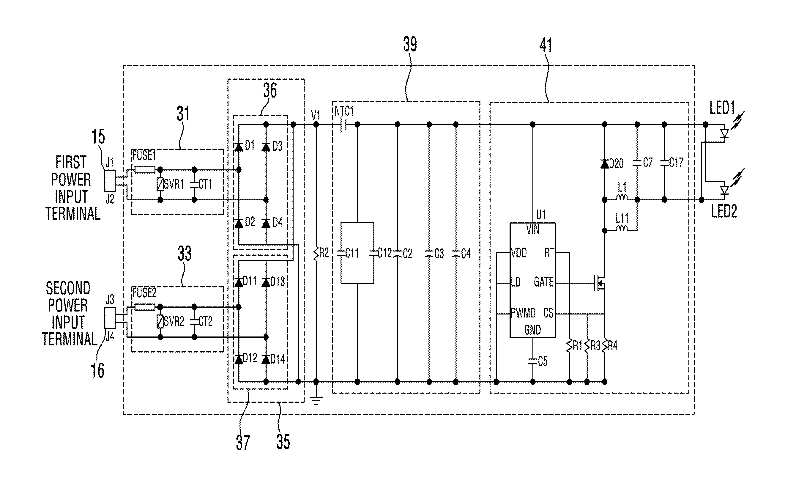
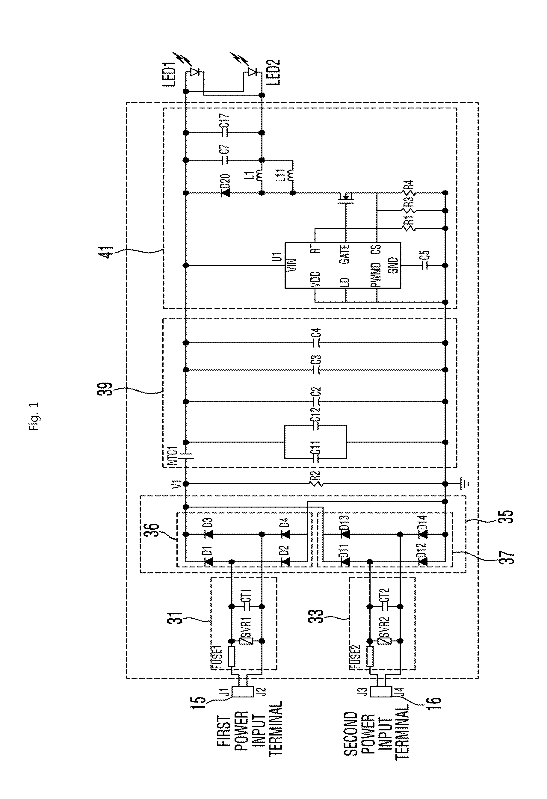
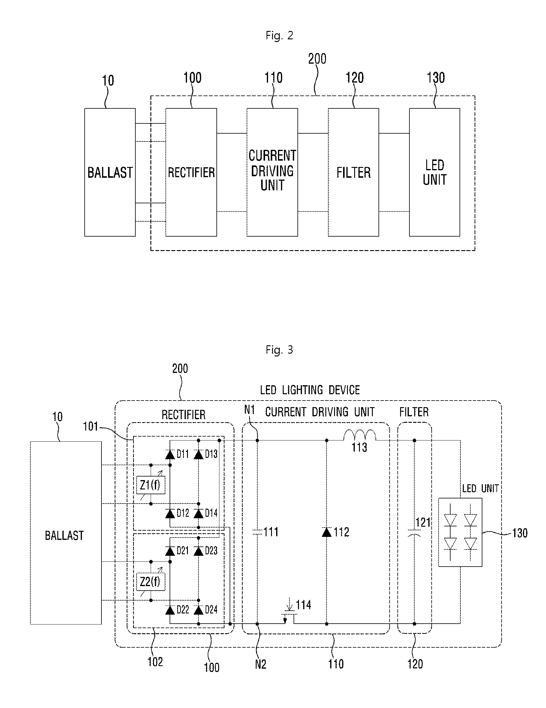
[0031]The following detailed description of the present invention shows a specified embodiment of the present invention and will be provided with reference to the accompanying drawings. The embodiment will be described in enough detail that those skilled in the art are able to embody the present invention. It should be understood that various embodiments of the present invention are different from each other and need not be mutually exclusive. For example, a specific shape, structure and properties, which are described in this disclosure, may be implemented in other embodiments without departing from the spirit and scope of the present invention with respect to one embodiment. Also, it should be noted that positions or placements of individual components within each disclosed embodiment may be changed without departing from the spirit and scope of the present invention. Therefore, the following detailed description is not intended to be limited. If adequately described, the scope of...


PUM


Abstract

An LED lighting device using a ballast may be provided that includes: an LED unit which includes at least one LED device; a rectifier which rectifies a current power signal output from the ballast; and a current driving unit which receives an output current of the rectifier and controls the power which is transmitted from the ballast to the LED unit. The current driving unit transmits current which has a magnitude greater than that of the output current of the rectifier to the LED unit.

Description

CROSS-REFERENCE TO RELATED APPLICATIONS[0001]This application claims priority to Korean Patent Application No. 10-2013-0019310, filed on Feb. 22, 2013, the contents of which are hereby incorporated by reference in their entirety into the present disclosure.BACKGROUND[0002]1. Field[0003]The present invention relates to an LED lighting device using a ballast[0004]2. Description of Related Art[0005]Recently, a light emitting diode (LED) is being increasingly used as a new lighting device in place of a filament bulb or a fluorescent lamp and becomes popular. The LED can be driven at a low voltage and has a longer life span, lower power consumption, a more rapid response speed and stronger crashworthiness than those of other lighting devices. The LED can become smaller and lighter. However, since the LED is activated by a very low direct current power and is turned on in a manner different from that of the fluorescent lamp, a general LED lamp cannot be applied as it is to a fluorescent l...

Claims


Application Information

Patent Timeline
IPC IPC(8): H05B33/08H05B44/00
CPCH05B33/0815H05B45/38H05B45/50H05B45/375H05B45/59H02M3/1582Y02B20/30H05B45/3578H05B45/40
Inventor CHOI, JAEYOUNGHAN, HEESEOK
Owner HIDEEP
Learn More