Method and display unit for displaying a driving condition of a vehicle and corresponding computer program product

Active Publication Date: 2014-08-14
ROBERT BOSCH GMBH
View PDF2 Cites 14 Cited by
  • Summary
  • Abstract
  • Description
  • Claims
  • Application Information

AI Technical Summary

Benefits of technology

The patent describes a speedometer that serves as a useful and intuitive tool for automobile drivers. The speedometer display is designed to closely match the calculations made by a human driver using visual cues, such as the time to impact or the distance to the preceding vehicle. The speedometer is particularly useful when used in combination with an Adaptive Cruise Control (ACC) system, which controls the distance to preceding vehicles. The system uses high-quality sensors to measure the distance to the vehicle and safely control it, displaying information on the speedometer to the driver. The system also includes a marking that is associated with a safe driving condition, which is the velocity of the vehicle at which there is no collision risk. This marking is shown in relation to the driver's current condition, making it easier for them to estimate the current driving situation. The display unit also displays an image of the object to help the driver understand the traffic situation.

Problems solved by technology

While the speedometer must always be given attention merely because of maintaining the speed limits, the tachometer display is not of interest for most drivers.
However, many drivers of manual transmission vehicles shift more according to sound than according to the tachometer.

Method used


Image

  • Method and display unit for displaying a driving condition of a vehicle and corresponding computer program product
  • Method and display unit for displaying a driving condition of a vehicle and corresponding computer program product
  • Method and display unit for displaying a driving condition of a vehicle and corresponding computer program product

Examples


Embodiment Construction

[0042]Identical or similar reference numerals are used for the similarly acting elements shown in the various figures in the following description of preferred exemplary embodiments of the present invention, a repeated description of these elements being omitted.

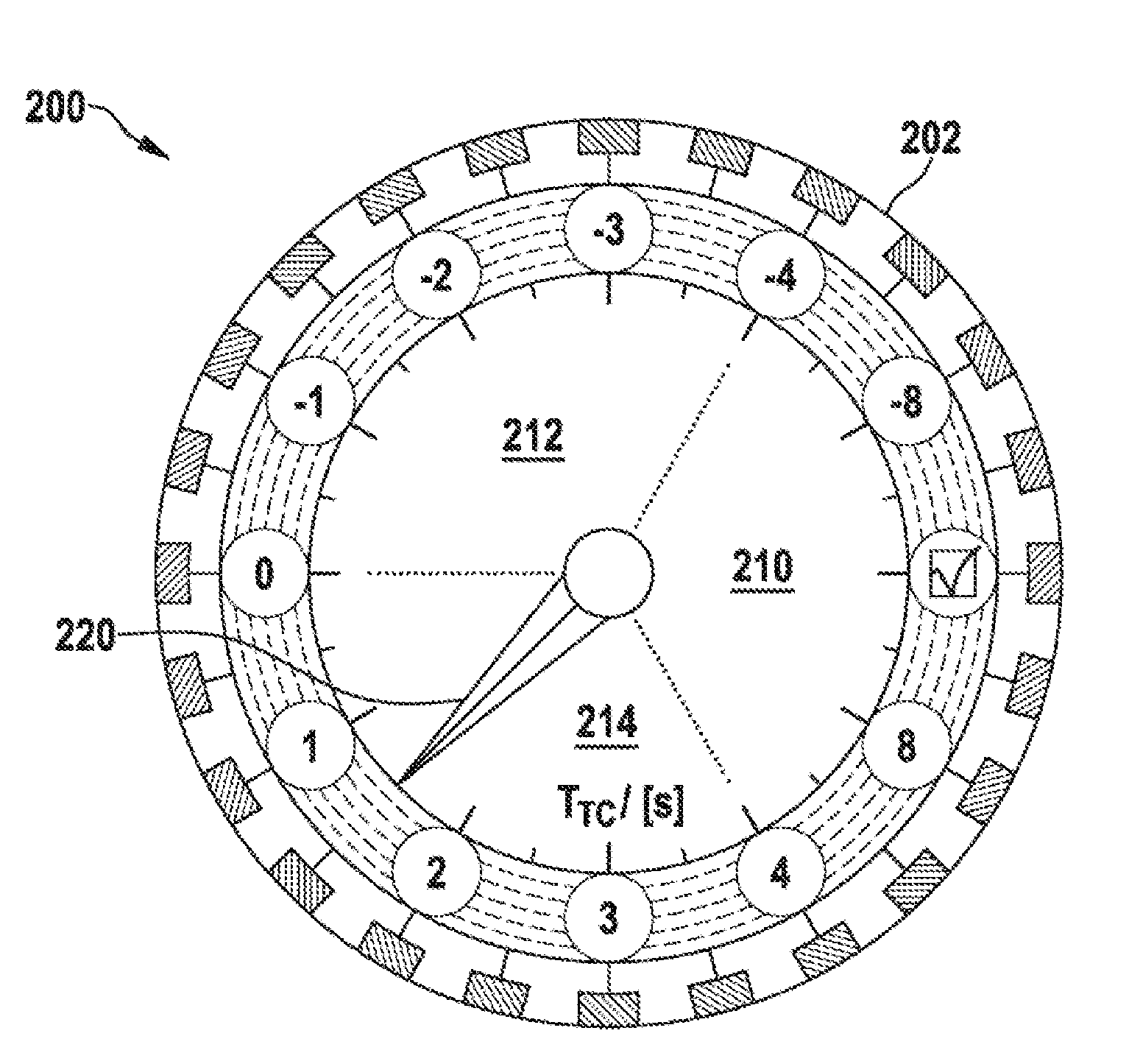
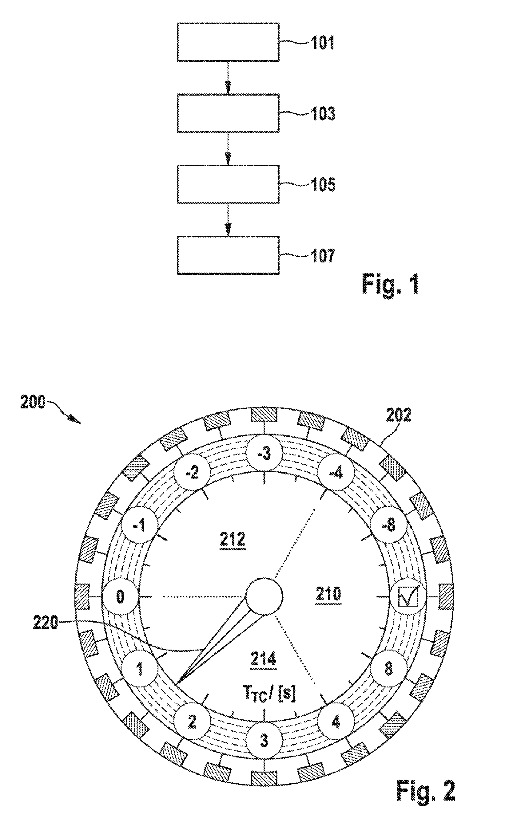
[0043]FIG. 1 shows a flow chart of a method for displaying a safe driving condition of a vehicle according to one exemplary embodiment of the present invention. In a step 101, a safe driving condition of the vehicle is ascertained, in which no risk of a collision with the other vehicle exists. In a step 103, a prevailing driving condition of the vehicle is ascertained. In a step 105, based on the safe driving condition and the prevailing driving condition, an item of control information for activating a display unit is determined, which is suitable for causing a display of an item of information about the prevailing driving condition in relation to an item of information about the safe driving condition by the display unit. ...


PUM


Abstract

A method for determining an item of control information for displaying a driving condition of a vehicle with the aid of a display unit includes: an ascertainment of the safe driving condition of the vehicle, in which no risk of a collision with an object exists; an ascertainment of a prevailing driving condition of the vehicle in relation to the safe driving condition is carried out; a determination of the item of control information for activating the display unit based on the safe driving condition and the prevailing driving condition, the item of control information causing a display of an item of information about the prevailing driving condition in relation to an item of information about the safe driving condition by the display unit.

Description

BACKGROUND OF THE INVENTION[0001]1. Field of the Invention[0002]The present invention relates to a method for displaying a driving condition of a vehicle, a display unit for displaying a driving condition of a vehicle, a corresponding device, and a corresponding computer program product.[0003]2. Description of the Related Art[0004]The dashboard of motor vehicles is usually dominated by two display instruments, the speedometer and the tachometer.[0005]U.S. Pat. No. 6,922,139 B2 describes a display instrument for a vehicle, using which the velocity associated with the vehicle, on the one hand, and the velocity relating to another vehicle, on the other hand, may be displayed.BRIEF SUMMARY OF THE INVENTION[0006]Against this background, the present invention provides a method for displaying a driving condition of a vehicle, a display unit for displaying a driving condition of a vehicle, a method for assisting a driver of a vehicle in a driving task with the aid of a display unit, further...

Claims


Application Information

Patent Timeline
IPC IPC(8): B60W50/14G01D7/02B60K37/02G01P1/08B60W30/095B60K35/00
CPCB60K35/00B60K2350/1064B60K2350/1084B60K2350/2056B60K2350/2065B60K2350/352B60K2350/403B60K2350/408B60W30/095G01P1/08B60K37/02G01D7/02B60W50/14B60W2050/146G01D2207/30G01S7/062G01S7/10G01S2013/9323G01S13/867B60K35/20B60K2360/1515B60K35/215B60K35/60B60K35/28B60K2360/179B60K2360/31B60K2360/347B60K35/81B60K2360/698
Inventor SIMON, STEPHAN
Owner ROBERT BOSCH GMBH
Why Eureka
Try Eureka