
Image display device

a display device and image technology, applied in the field of image display devices, can solve the problems of inability to achieve appropriate color correction of display images, inability to measure such a detailed spectrum,

Active Publication Date: 2014-07-10
SEIKO EPSON CORP
View PDF10 Cites 13 Cited by
  • Summary
  • Abstract
  • Description
  • Claims
  • Application Information

AI Technical Summary

Benefits of technology

The patent describes a configuration where a display has a special element that allows for accurate detection of light in different colors. This element is called a spectroscopic element. The display also has a photometric section that can be moved from the edge to the display area. When the display is showing normal images, the photometric section can be moved to the edge to not interfere with the display. The technical effect of this configuration is that it allows for accurate color correction based on the detection of light in different colors, and ensures that the display is not obstructed during normal use.

Problems solved by technology

Such a photosensor or a photodiode can only measure the limited color information such as RGB components, and is not capable of measuring such a detailed spectrum as described above.
Therefore, in the display device using such a measurement device as described above, there is a problem that an appropriate color correction of the display image is not achievable.

Method used


Image

  • Image display device
  • Image display device
  • Image display device

Examples


Embodiment Construction

[0038]An image display device according to an embodiment of the invention will hereinafter be explained with reference to the accompanying drawings.

[0039]Overall Configuration of Image Display Device

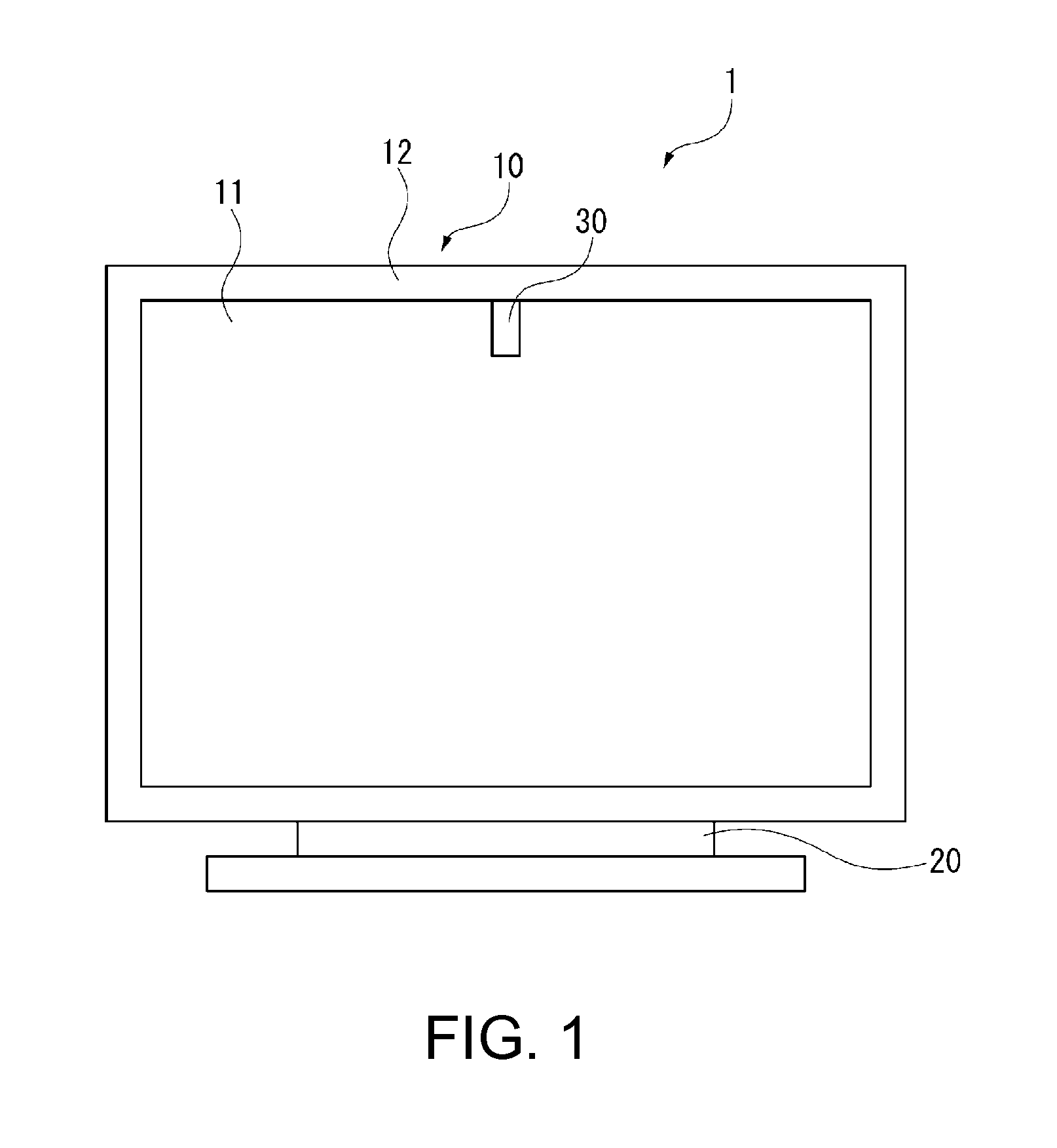
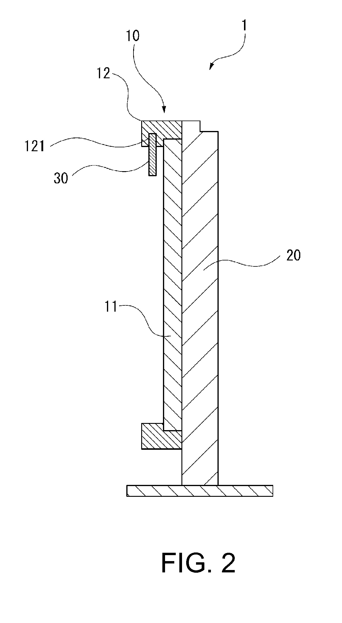
[0040]FIG. 1 is a front view showing an overview of the image display device according to the present embodiment. FIG. 2 is a cross-sectional view of the image display device according to the present embodiment.

[0041]In FIG. 1, the image display device 1 according to the present embodiment is provided with a display section 10 for displaying an image, and an exterior section 20 for holding the display section 10.

[0042]As shown in FIGS. 1 and 2, the display section 10 is provided with a display 11 as a display area, and a bezel section 12 for holding the display 11.

[0043]The display 11 can be formed of any display panel such as a liquid crystal panel, a plasma display panel (PDP), or an organic EL.

[0044]The bezel section 12 is a frame member for holding the outer peripheral portion of the...


PUM


Abstract

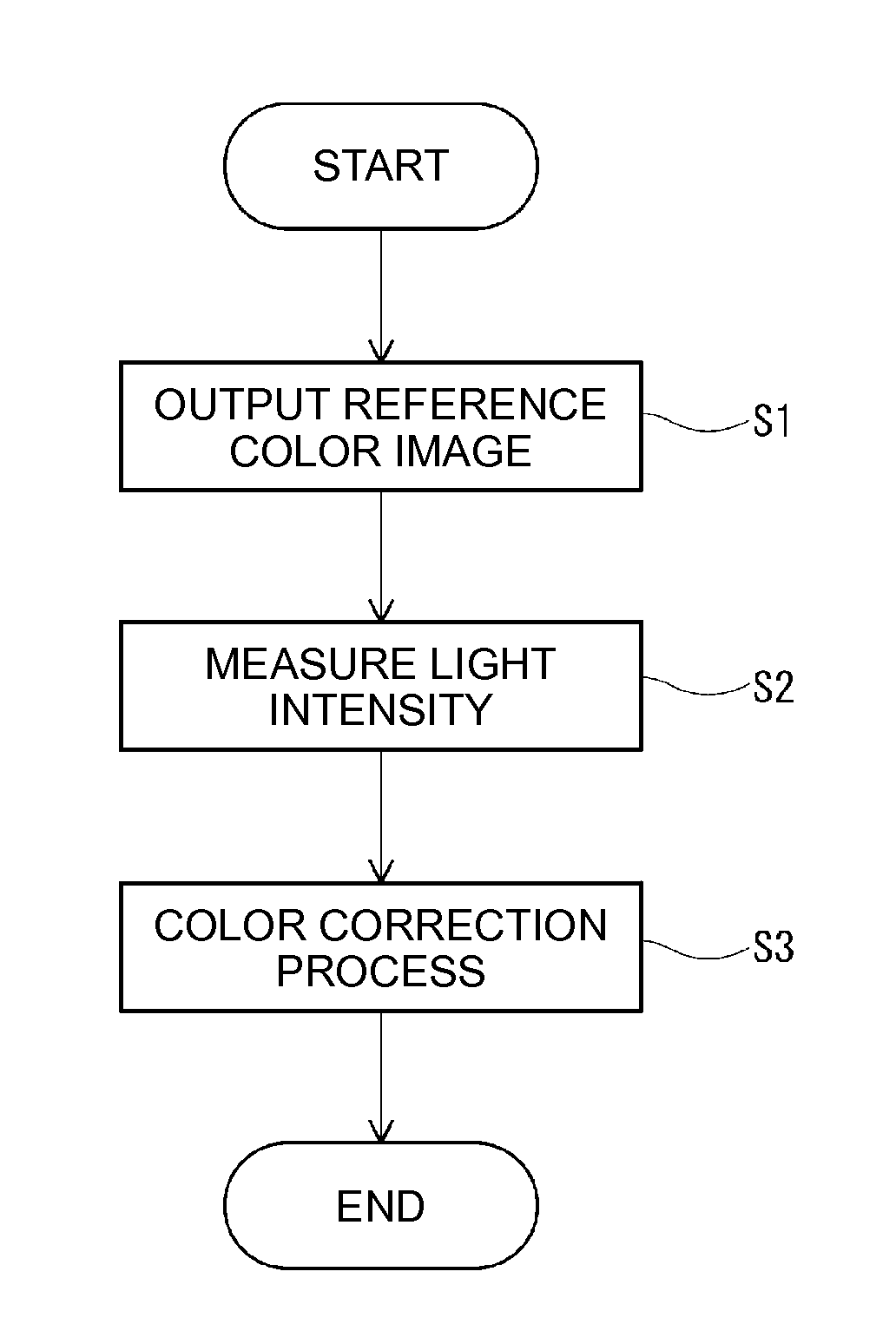
An image display device includes a display section adapted to display an image, a photometric section including a variable wavelength interference filter adapted to transmit light with a predetermined wavelength from incident light and a photosensor adapted to detect light obtained by dispersion, and disposed so as to be opposed to the display section, and a control section adapted to control the display section and the photometric section, and the control section obtains a spectrum of the incident light based on light intensity of the light detected by the photosensor, and then performs a color correction of the display section based on the spectrum.

Description

BACKGROUND[0001]1. Technical Field[0002]The present invention relates to an image display device.[0003]2. Related Art[0004]In the past, there has been known a display device, which measures a feature quantity such as the luminance of an image displayed to adjust display colors (see, e.g., JP-A-2005-208548 (Document 1)).[0005]The display device described in Document 1 is provided with a photometric device retractably projecting from a bezel to a display area. The photometric device is provided with a photosensor and a photodetector opposed to a display screen, and the display device corrects the display colors based on a measurement result of the photometric device.[0006]Incidentally, in order to appropriately correct the colors of the image displayed on the display device, it is necessary to accurately measure the colors of the image displayed. In the case of, for example, using a liquid crystal display device as the display device, a cold-cathode tube is used as the backlight, and ...

Claims


Application Information

Patent Timeline
Patent Type & Authority Applications(United States)
IPC IPC(8): G09G5/02
CPCG09G5/02G06F1/1601G09G2320/0693G09G2360/144G09G2360/145
Inventor GOMI, TSUGIOSAKURAI, KAZUNORI
Owner SEIKO EPSON CORP
Learn More