Orthogonality compensation method for length measurement device and length measurement device using same

a compensation method and measurement device technology, applied in measurement devices, instruments, surveying and navigation, etc., can solve problems such as measurement errors and affecting subsequent manufacturing operations, and achieve the effect of ensuring measurement accuracy

Inactive Publication Date: 2014-07-03
SHENZHEN CHINA STAR OPTOELECTRONICS TECH CO LTD
View PDF10 Cites 4 Cited by
  • Summary
  • Abstract
  • Description
  • Claims
  • Application Information

AI Technical Summary

Benefits of technology

[0037]The efficacy of the present invention is that the present invention provides an orthogonality compensation method for length measurement device and a length measurement device using same, wherein alignment marks are provided on the measuring table and the coordinates of the alignment marks are first read before measurement is carried out in order to compare the coordinates with the coordinates that are set for the alignment marks so that correction can be automatically done with variation occurs to ensure the orthogonality between X-axis and Y-axis and thus ensuring accuracy of measurement.

Problems solved by technology

However, in a process of actual measurement, when the cross bar 508 slides with respect to the guide rails 506, variation of orthogonality between the cross bar 508 and the guide rails 506 may occur (see FIG. 6), leading to errors of measurement and thus affecting the subsequent manufacturing operations.

Method used


Image

  • Orthogonality compensation method for length measurement device and length measurement device using same
  • Orthogonality compensation method for length measurement device and length measurement device using same
  • Orthogonality compensation method for length measurement device and length measurement device using same

Examples


Embodiment Construction

[0049]To further expound the technical solution adopted in the present invention and the advantages thereof, a detailed description is given to a preferred embodiment of the present invention and the attached drawings.

[0050]Referring to FIGS. 7-9, the present invention provides an orthogonality compensation method for length measurement device, which comprises the following steps:

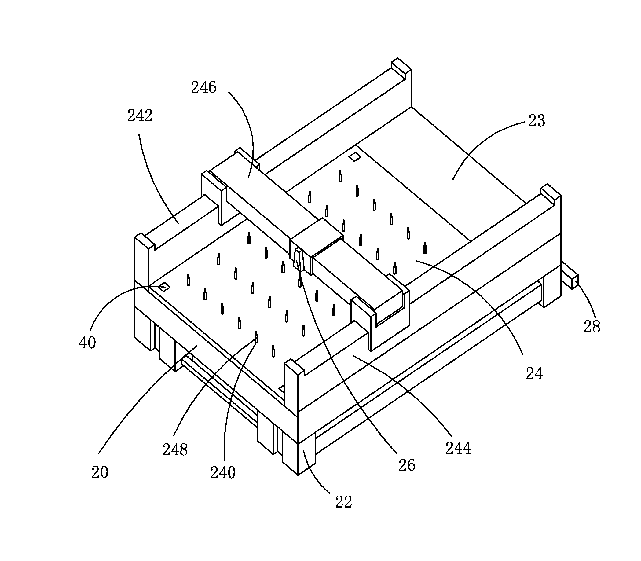
[0051]Step 1: providing a measuring platform 20 and a plurality of alignment marks 40, wherein the measuring platform 20 comprises a chassis 22, a rectangular measuring table 24 mounted on the chassis 22, an inspection microscope 26 arranged above the measuring table 24, and a laser device 28 mounted on the chassis 22 and coupled to the inspection microscope 26.

[0052]The measuring platform 20 further comprises first and second guide rails 242, 244 that are mounted on the measuring table 24 and are respectively located at two opposite sides of the measuring table 24 and a cross bar 246 mounted on the first a...


PUM


Abstract

The present invention provides an orthogonality compensation method for length measurement device, including: providing a measuring platform and a plurality of alignment marks, wherein the measuring platform comprises a chassis, a rectangular measuring table mounted on the chassis, an inspection microscope arranged above the measuring table, and a laser device mounted on the chassis and coupled to the inspection microscope; mounting the alignment marks on the measuring table and recording the coordinates of the alignment marks with respect to the coordinate system of the measuring table to provide reference coordinates; using the inspection microscope to read actual coordinates of the alignment marks with respect to the coordinate system of the measuring table and comparing the actual coordinates with the reference coordinates; and carrying out correction of coordinates if differences exist between the actual coordinates and the reference coordinates, so as to make the actual coordinates equal to the reference coordinates.

Description

BACKGROUND OF THE INVENTION[0001]1. Field of the Invention[0002]The present invention relates to the field of measurement, and in particular to an orthogonality compensation method for length measurement device and a length measurement device using the method.[0003]2. The Related Arts[0004]Liquid crystal display (LCD) has a variety of advantages, such as thin device body, low power consumption, and being free of radiation, and is thus widely used. Most of the LCDs that are currently available in the market are backlighting LCDs, which comprise a liquid crystal display panel and a backlight module. The operative principle of the liquid crystal panel is that liquid crystal molecules are interposed between two parallel glass substrates and the liquid crystal molecules are controlled to change direction by applying electricity to a circuit of the glass substrates in order to refract out light emitting from the backlight module for generating images.[0005]Referring to FIG. 1, the liquid ...

Claims


Application Information

Patent Timeline
Patent Type & Authority Applications(United States)
IPC IPC(8): G01B11/02G01B11/27
CPCG01B11/272G01B11/02G01B21/045G01B11/043
Inventor LIN, YUNGYU
Owner SHENZHEN CHINA STAR OPTOELECTRONICS TECH CO LTD
Why Eureka
Try Eureka