Orthopedic bonding agent application tool

a technology of application tool and application tool, which is applied in the field of orthopaedic joint replacement procedure, can solve the problems of limiting the life of the replacement joint, and achieve the effect of improving the procedure of orthopaedic joint replacemen

Active Publication Date: 2014-05-15
TIPIRNENI SOFTWARE LLC
View PDF6 Cites 3 Cited by
  • Summary
  • Abstract
  • Description
  • Claims
  • Application Information

AI Technical Summary

Benefits of technology

[0003]In accordance with various embodiments, the present disclosure includes a tool for an improved orthopedic joint replacement procedure, wherein the tool aids in the injection of the bonding agent. An apparatus for aiding in an orthopedic joint replacement may comprise a handle portion for gripping a head portion that may contain a bonding agent. The head portion may further comprise a base plate, an external wall and a plurality of cells within the external wall defined by internal walls. The handle may be attached at one end to one of at least the exterior side of the external wall or the baseplate. At least one or more of the plurality of cells may include a through hole at the bottom of the cell. A portion of the plurality of cells may be similarly shaped. A portion of the plurality of cells may be dissimilarly shaped. The similarly shaped cells may be honeycomb shaped. The dissimilarly shaped cells may connect the honeycomb shaped cells to the external side wall. The head may conform to the shape of the bone (e.g., end of the bone) for which the head is applied. The head may be shaped similar to the distal end of the femur. The head may be shaped similar to the proximal end of the tibia. The head may be a “bean” shape (e.g., oblong with a convex side and a concave side, and rounded on the ends) and slightly larger than the distal end of the femur. The side wall of the baseplate may further comprise a rib wrapping around at least half of the tool on the side nearest to the handle. The external wall may also further comprise holes. While described herein with the end of the bone, the tool may be applied to any surface of the bone.
[0004]In accordance with various embodiments, the present disclosure includes a method for applying a bonding agent to a bone that is prepared to receive the bonding agent as part of a joint replacement procedure. The method may include obtaining a bonding agent application tool comprising a handle and a head. The head may comprise a base plate and a plurality of cells. The cells may be filled with the bonding agent. The top of the walls of the plurality of cells may be placed against the prepared bone end where the joint is being replaced. A force may be applied to the base plate forcing the cells to cut into the bone and forcing the bonding agent into the cuts and pores in the bone. The force may be applied to the baseplate by striking the baseplate with a mallet. The tool may be removed from the end of the bone. The replacement joint may be oriented in the area prepared with the bonding agent. The method may be repeated for the second bone in the joint. The first bone may be the distal end of the femur and the second bone may be the proximal end of the tibia.

Problems solved by technology

This premature breakdown of the bond unnecessarily limits the life of the replacement joint.

Method used


Image

  • Orthopedic bonding agent application tool
  • Orthopedic bonding agent application tool
  • Orthopedic bonding agent application tool

Examples


Embodiment Construction

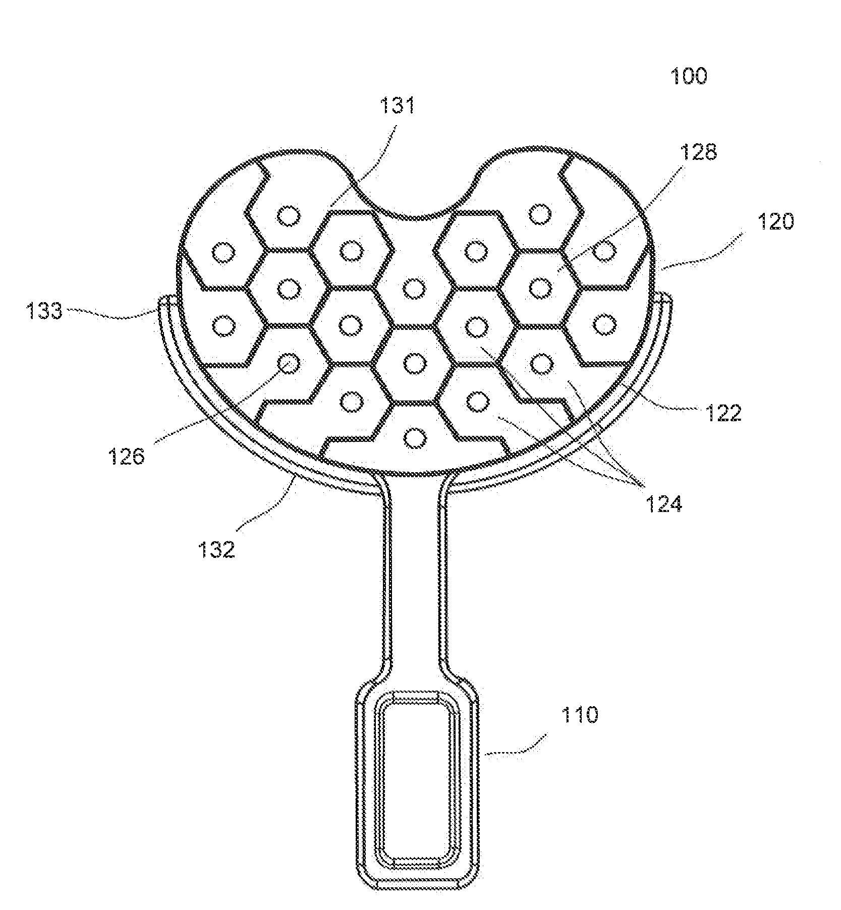
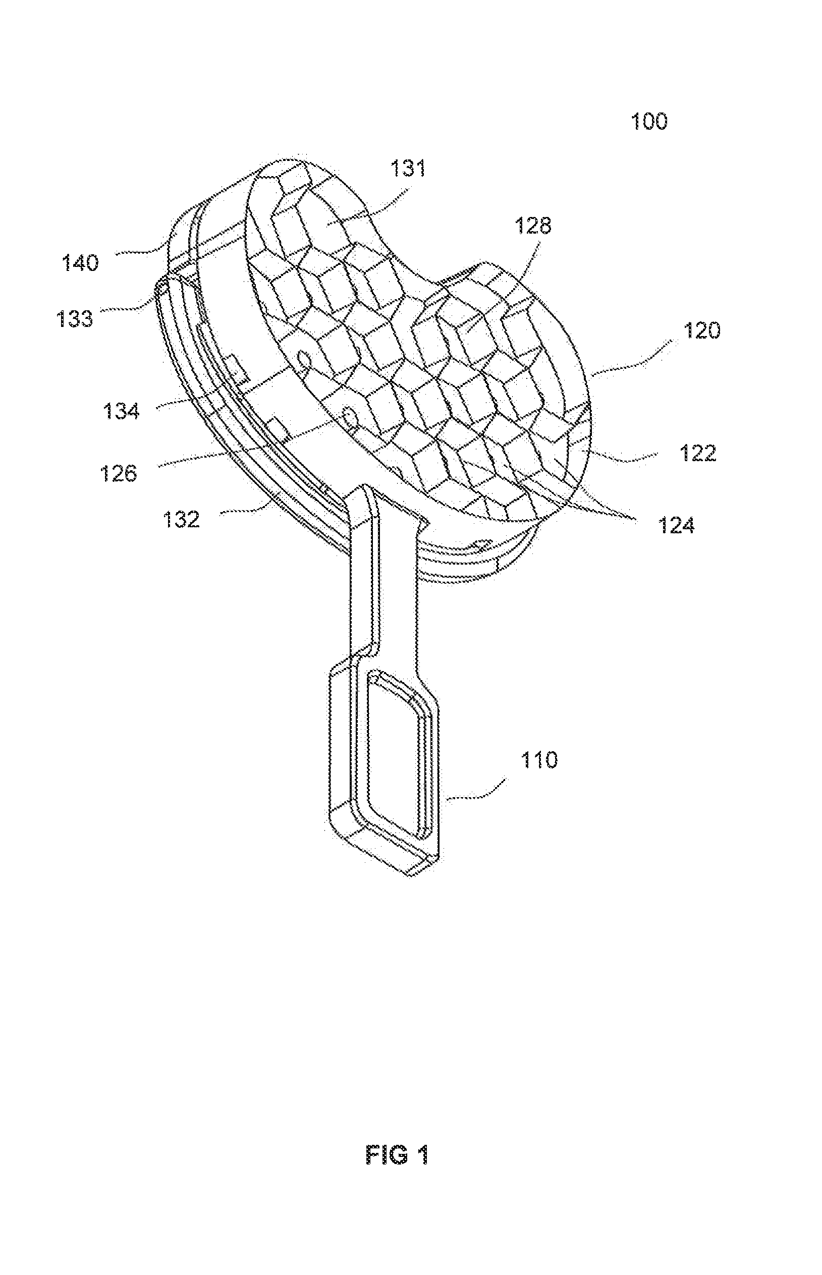
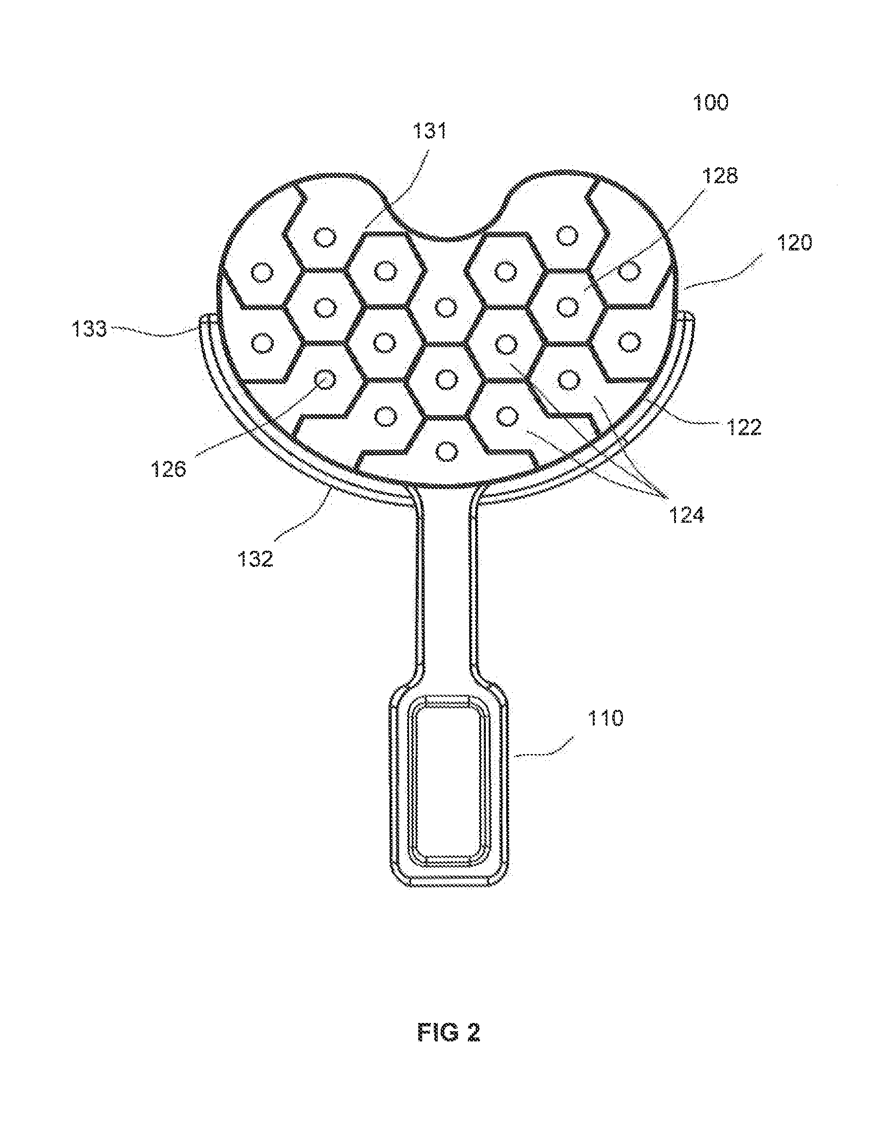
[0021]The detailed description of exemplary embodiments herein makes reference to the accompanying drawings, which show exemplary embodiments by way of illustration and its best mode. While these exemplary embodiments are described in sufficient detail to enable those skilled in the art to practice the invention, it should be understood that other embodiments may be realized and that logical, chemical and mechanical changes may be made without departing from the spirit and scope of the invention. Thus, the detailed description herein is presented for purposes of illustration only and not of limitation. For example, the steps recited in any of the method or process descriptions may be executed in any order and are not necessarily limited to the order presented. Moreover, many of the functions or steps may be outsourced to or performed by one or more third parties. Furthermore, any reference to singular includes plural embodiments, and any reference to more than one component or step ...


PUM


Abstract

The present disclosure relates to a tool for injecting a bonding agent into the prepared end of a bone for bonding a joint replacement device to the bone. The tool incorporates vented cells for containing the bonding agent. Force is applied to the back of the tool, while placing the front of the tool filled with bonding agent against the prepared bone area. The force causes the cells to cut into the end of the prepared bone. The force also causes the bonding agent to be forced deep into the cuts and pores of the bone.

Description

FIELD OF DISCLOSURE[0001]The present disclosure relates generally to a tool for aiding in the injection of bonding agent into the knee during knee replacements.BACKGROUND OF THE DISCLOSURE[0002]Joint replacement surgery is usually performed on patients that have damage to the surface of the bones that make up the joint. For example, in knee replacement surgery, a femoral and / or a tibial replacement joint provides a new surface contact in the joint. During application of the replacement surfaces, a bonding agent (e.g., polymethylmethacrylate cement) is used to attach the replacement joint to the bone. A major shortcoming of the joint replacement surgery is that the bond between the replacement joint and the bone tends to breakdown quicker than the replacement joint. This premature breakdown of the bond unnecessarily limits the life of the replacement joint.SUMMARY OF THE DISCLOSURE[0003]In accordance with various embodiments, the present disclosure includes a tool for an improved ort...

Claims


Application Information

Patent Timeline
Patent Type & Authority Applications(United States)
IPC IPC(8): A61B17/88
CPCA61B17/8805A61B17/8827A61B17/00491A61F2/46A61F2002/4631
Inventor TIPIRNENI, KISHORE
Owner TIPIRNENI SOFTWARE LLC
Why Eureka
Try Eureka