Method for calculating spacing ratio of interferometer array antenna for direction finder

a technology of interferometer array antenna and spacing ratio, which is applied in the direction of direction finders, radio wave direction/deviation determination systems, instruments, etc., can solve the problem of not considering the phase difference shift generated in the direction finder

Active Publication Date: 2014-04-17
AGENCY FOR DEFENSE DEV
View PDF3 Cites 3 Cited by
  • Summary
  • Abstract
  • Description
  • Claims
  • Application Information

AI Technical Summary

Benefits of technology

[0025]A method for calculating a spacing ratio of an interferometer array antenna for a direction finder may facilitate for setting an antenna spacing of the array antenna in spite of system complexity or affection by a payload platform.

Problems solved by technology

The first method requires complicated processes and the second method is simple but has a disadvantage that phase difference shift which is generated in a direction finder is not considered.

Method used


Image

  • Method for calculating spacing ratio of interferometer array antenna for direction finder
  • Method for calculating spacing ratio of interferometer array antenna for direction finder
  • Method for calculating spacing ratio of interferometer array antenna for direction finder

Examples


Embodiment Construction

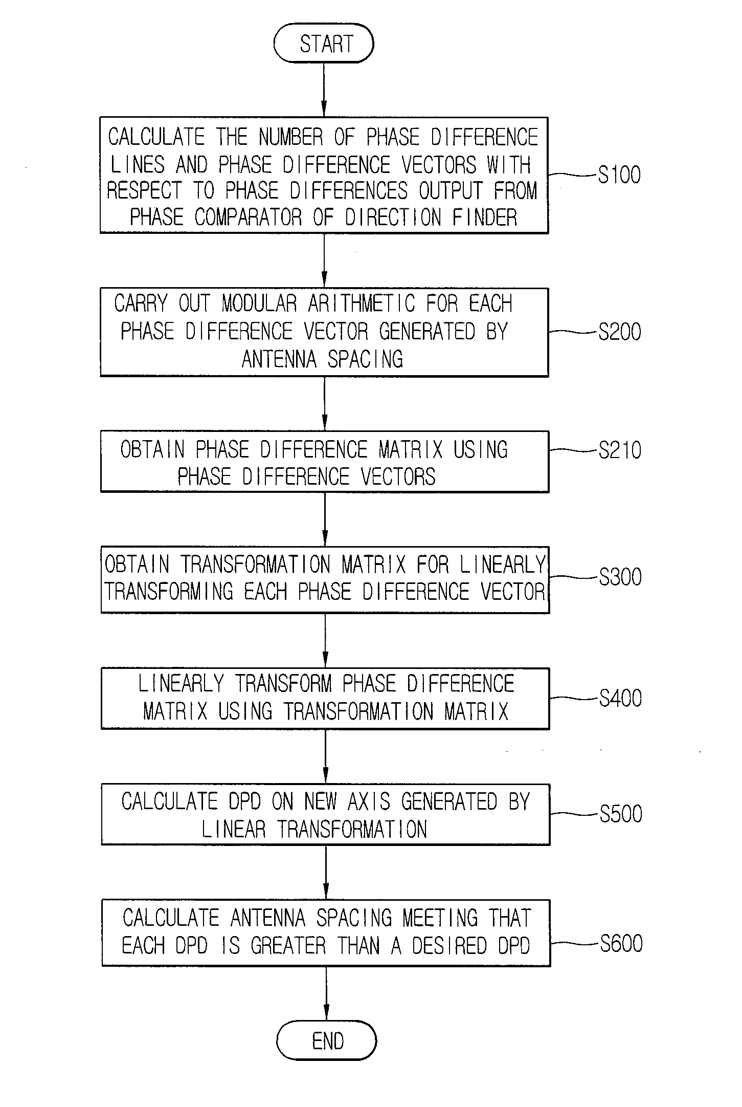
[0036]Description will now be given in detail of a method for calculating a spacing ratio of an interferometer array antenna for finding direction according to the exemplary embodiments, with reference to the accompanying drawings. Hereinafter, suffixes “module” and “unit or portion” for components used herein in description are merely provided only for facilitation of preparing this specification, and thus they are not granted a specific meaning or function. Hence, it should be noticed that “module” and “unit or portion” can be used together. For the sake of brief description with reference to the drawings, the same or equivalent components will be provided with the same reference numbers, and description thereof will not be repeated. The expression in the singular form in this specification will cover the expression in the plural form unless otherwise indicated obviously from the context.

[0037]The present disclosure is applied to a method for calculating a spacing of an interferom...


PUM


Abstract

A method for calculating a spacing between antenna elements of an interferometer array antenna includes setting an azimuth of an instantaneous field of view and a distance between phase differences, and obtaining the number of phase difference lines and phase difference vectors with respect to the phase differences of the signals output in a phase comparator of a direction finder, performing a modular arithmetic for the phase difference vectors to obtain phase difference matrixes, obtaining a transformation matrix for linearly transforming the phase difference matrixes and performing the linear transformation using the transformation matrix, calculating a distance between the phase differences on a new axis generated by the linear transformation, and calculating an antenna spacing as an array spacing of the array antenna, the antenna spacing meeting that the distance between the phase differences is greater than a desired distance between phase differences.

Description

CROSS-REFERENCE TO RELATED APPLICATIONS[0001]Pursuant to 35 U.S.C. §119(a), this application claims the benefit of earlier filing date and right of priority to Korean Application No. 10-2012-0114951, filed on Oct. 16, 2012 the contents of which is incorporated by reference herein in its entirety.BACKGROUND OF THE INVENTION[0002]1. Field of the Invention[0003]This specification relates to a method for calculating a spacing ratio of an interferometer array antenna which finds a direction through phase comparison.[0004]2. Background of the Invention[0005]In general, a direction finder is a receiving apparatus which measures a direction that electric waves are coming, and also referred to as a radio direction finder. The direction finder does not emit electric waves (radio waves) unlike radar. The direction finder is used for safety of ships and aircrafts and for identifying or monitoring unidentified or unlawful radio waves.[0006]The direction finder includes an antenna for receiving a...

Claims


Application Information

Patent Timeline
Patent Type & Authority Applications(United States)
IPC IPC(8): G01S3/46
CPCG01S3/46G01S3/48G01S3/12G01S3/14
Inventor LEE, JUNG HOONJOO, JEUNG MIN
Owner AGENCY FOR DEFENSE DEV
Why Eureka
Try Eureka