Slip Bracket Connector for Rigid Members
a technology of rigid members and connectors, applied in the direction of rod connections, couplings, manufacturing tools, etc., can solve the problem of connecting the connector to the first member without securely attaching i
- Summary
- Abstract
- Description
- Claims
- Application Information
AI Technical Summary
Benefits of technology
Problems solved by technology
Method used
Image

Examples
first embodiment
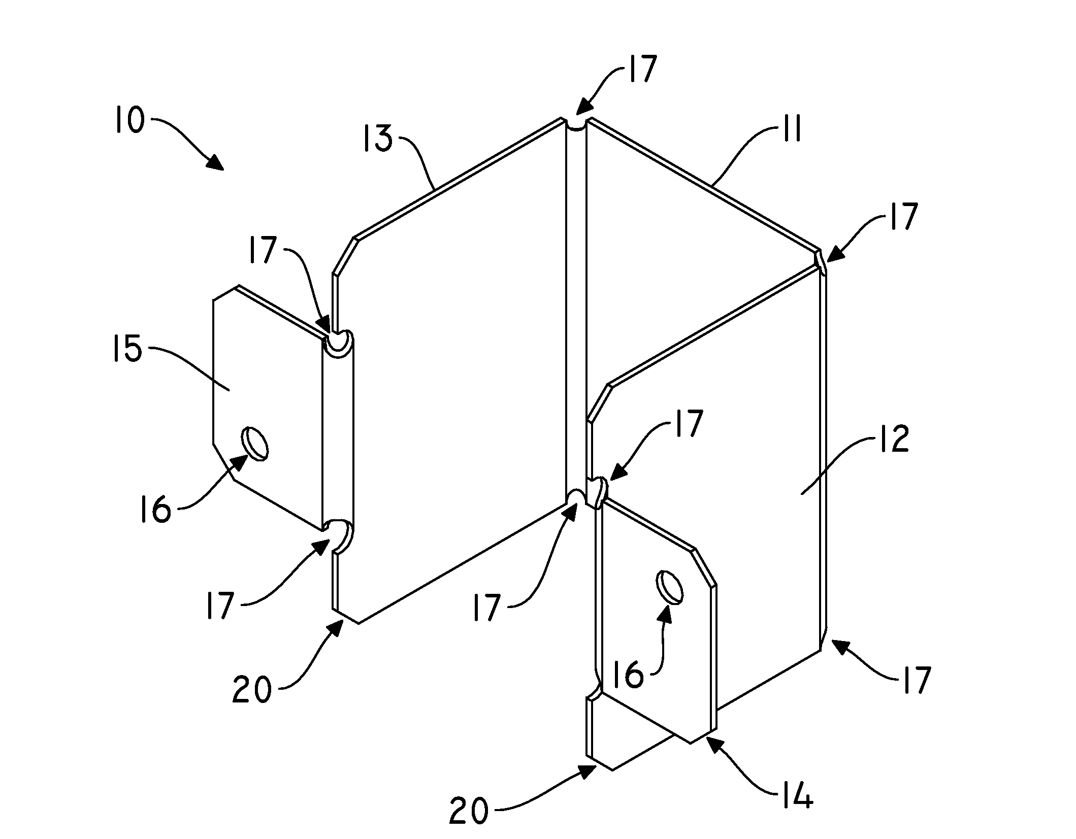
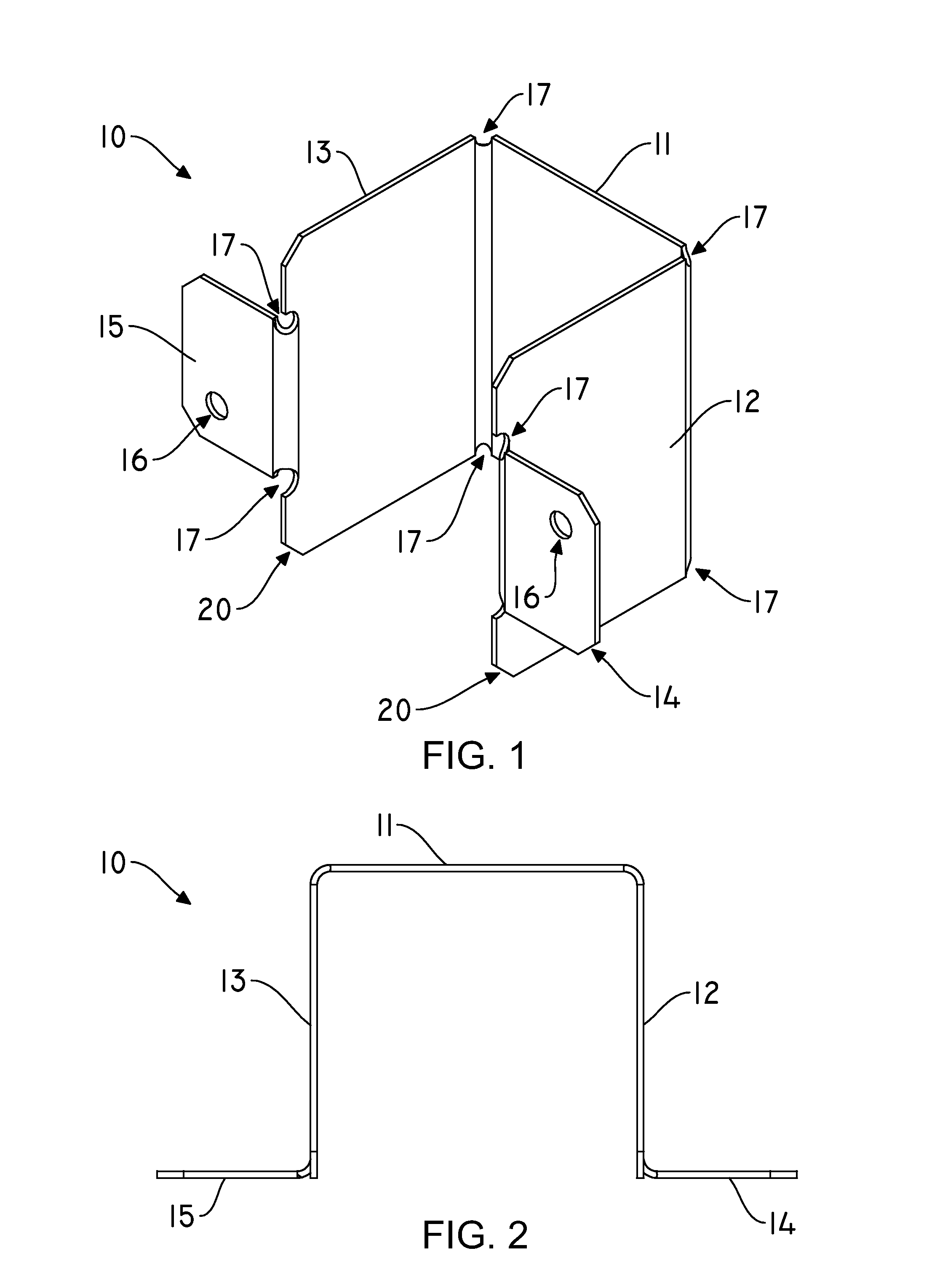
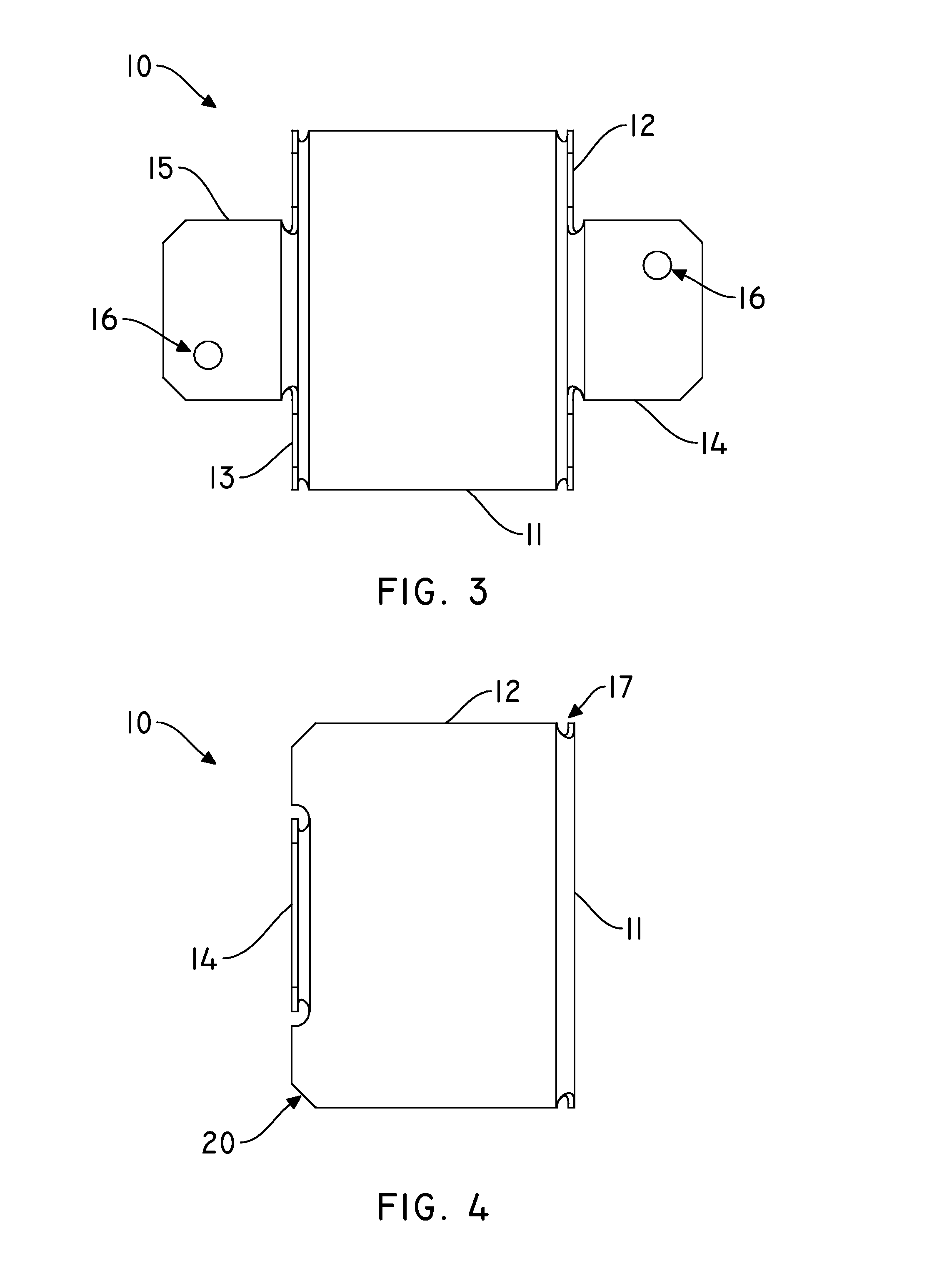
[0020]Referring to FIGS. 1-5, there is illustrated the present invention designated generally as 10 which is a one-piece bracket connector used to attach a first wood member to a second wood member while allowing the first wood member to fluctuate dimensionally according to the environment and the natural properties of the wood. A front portion 11 is attached to, and preferably integral with, a left portion 12 and a right portion 13 to form a three-sided brace. Preferably, the left and right portions 12, 13 are perpendicular to the front portion 11 and parallel to each other so that the brace is u-shaped. See FIG. 2. Alternatively, one or both of the left and right portions 12, 13 may intersect the front portion 11 at an acute or obtuse angle to accommodate non-square, non-rectangular first wood members, such as trapezoidal beams. The left and right portions 12, 13 may alternatively intersect each other to form a triangular beam having an apex at the intersection of the portions 12,...
second embodiment
[0026]The illustrated second embodiment of the device 10 may be stamped out of sheet metal as shown in FIG. 11. Stress relief punches 17 may be formed at each juncture of the components to facilitate bending of the sheet into the proper device 10 configuration without imparting undue stress on the components. Preferably, the stamped metal is folded at 90 degree angles up out of the page at first and second up-fold lines 21, 22 and third and fourth up-fold lines 31, 32, and folded at 90 degree angles down into the page at first and second down-fold lines 23, 24. Each bend requires a material bend allowance to maintain proper final dimensions after bending of the part is accomplished. Rear corners 20 of the right and left portions 12, 13 may be linearly cut or rounded to prevent damage or injury from the sharp corner.
[0027]The inventive device 10 may be applied in any scenario where restricting the dimensional fluctuations of the first wood member is best avoided. FIG. 12 illustrates ...
PUM
| Property | Measurement | Unit |
|---|---|---|
| Force | aaaaa | aaaaa |
Abstract
Description
Claims
Application Information
 - R&D
- Intellectual Property
- Life Sciences
- Materials
- Tech Scout
- Unparalleled Data Quality
- Higher Quality Content
- 60% Fewer Hallucinations
Browse by: Latest US Patents, China's latest patents, Technical Efficacy Thesaurus, Application Domain, Technology Topic, Popular Technical Reports.
© 2025 PatSnap. All rights reserved.Legal|Privacy policy|Modern Slavery Act Transparency Statement|Sitemap|About US| Contact US: help@patsnap.com