
Firearm receiver assemlby

a receiver and firearm technology, applied in the field of firearms, can solve the problems of compromising the zero of the weapon, the handguard used in the free floating design of the handguard, and the unsatisfactory mounting of secondary devices such as lights, lasers and optics

Active Publication Date: 2014-03-20
LWRC INTERNATIONAL
View PDF25 Cites 57 Cited by
  • Summary
  • Abstract
  • Description
  • Claims
  • Application Information

AI Technical Summary

Benefits of technology

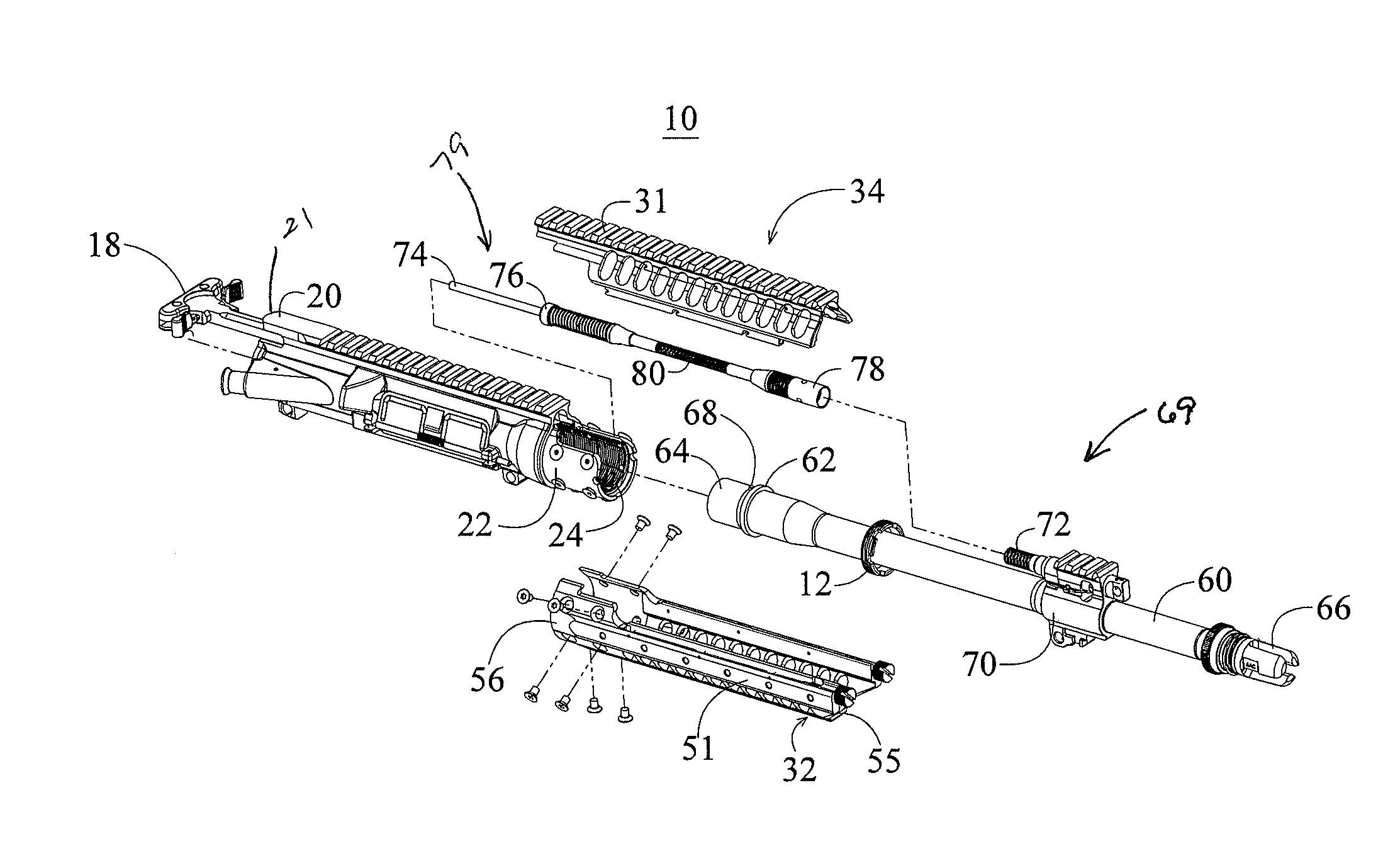
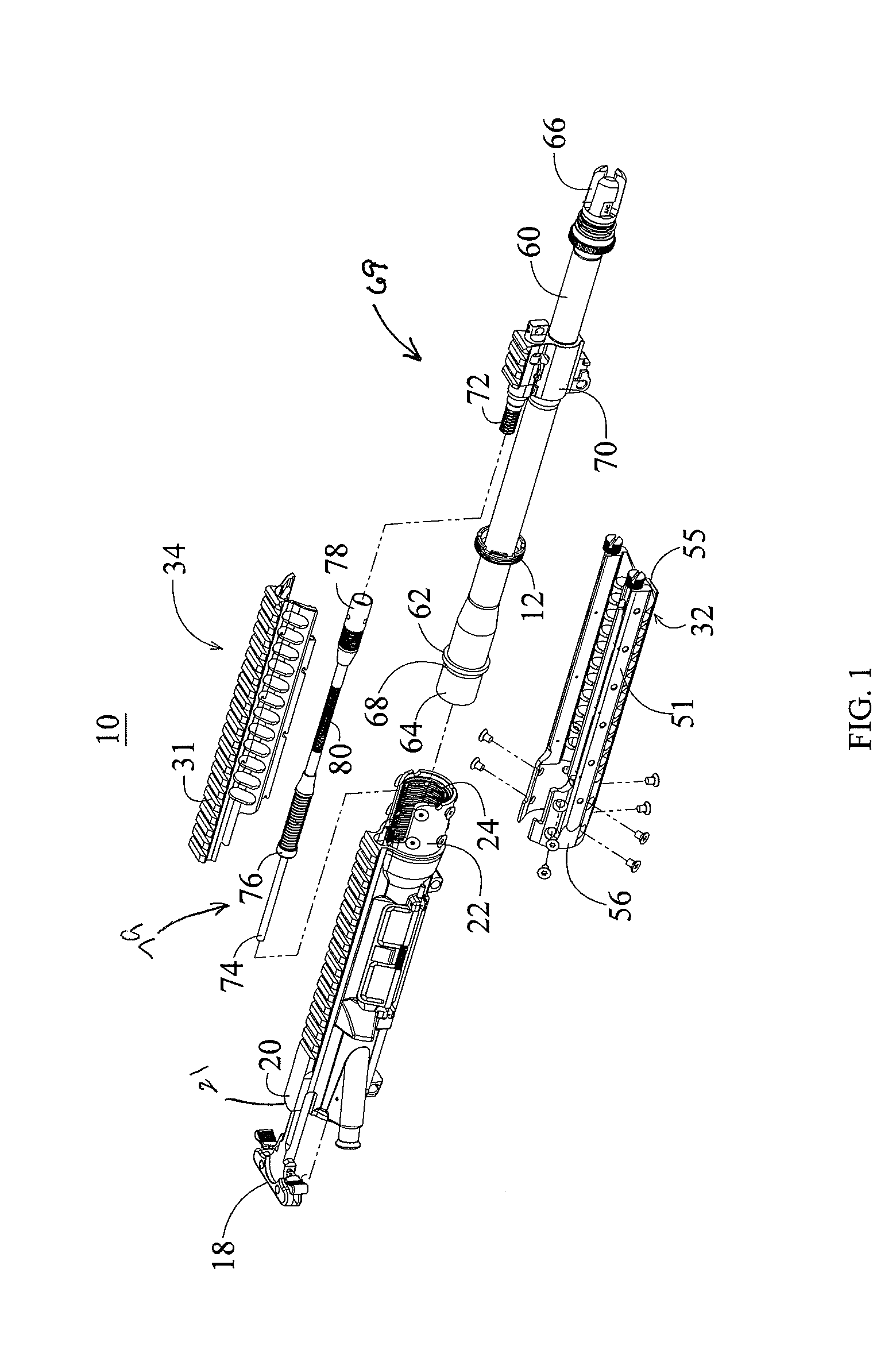
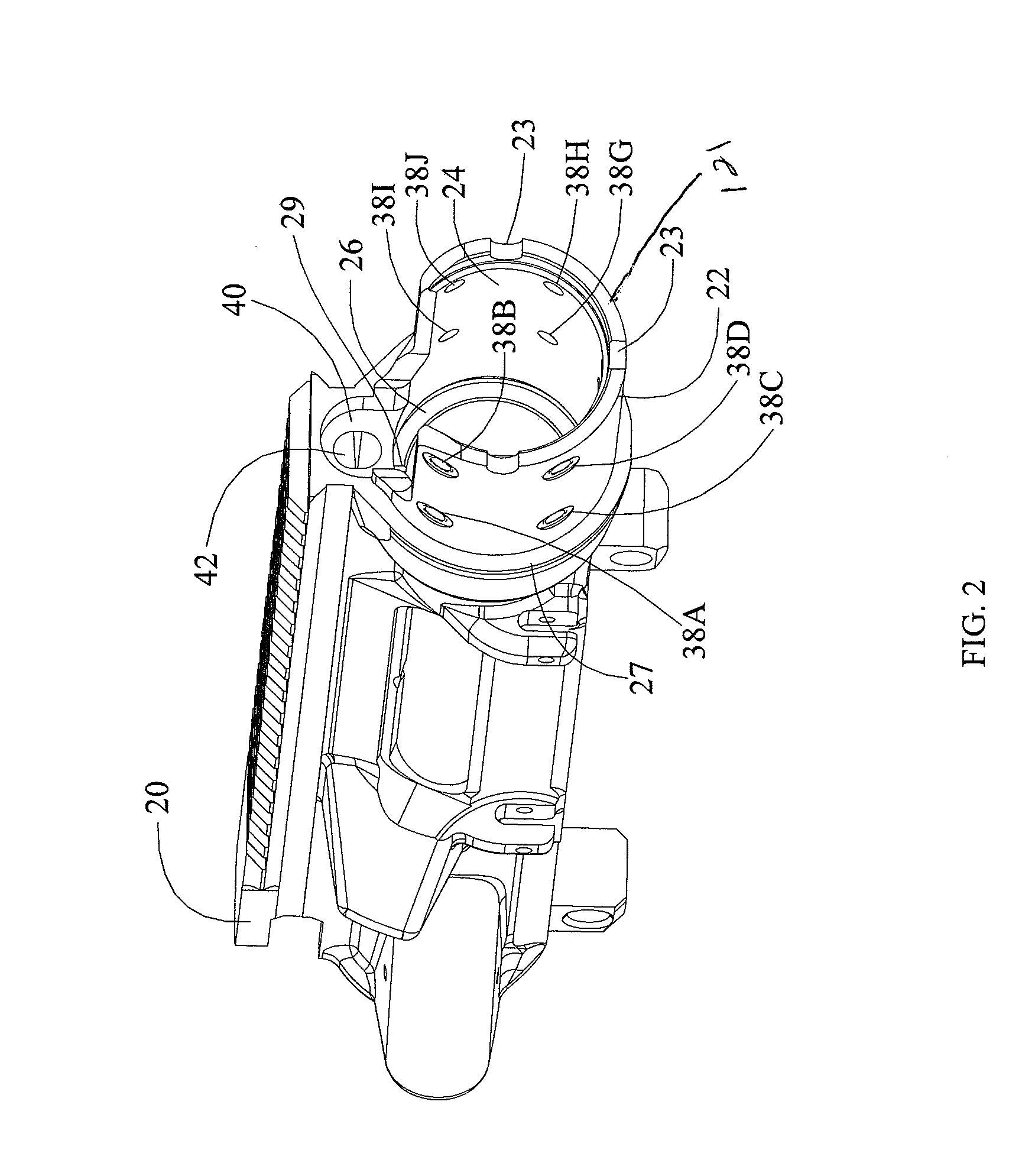
The present invention is an upper receiver assembly for M16 / AR15 type weapons that allows for direct mounting of the barrel and handguard assembly to the receiver extension, independently of each other. The assembly includes an upper receiver with a receiver extension, a handguard assembly, a piston assembly, and a barrel assembly. The handguard assembly has a top and bottom segment that are secured to the receiver extension using fasteners. The barrel assembly has an integral barrel nut that is threaded for coupling with a lock ring to secure the barrel directly to the receiver extension. The upper receiver provides a mounting point for the gas operating system of the firearm and also supports the gas piston assembly. The locknut has a grippable structure that is engageable with a specialized wrench to apply torque to the locknut. The invention simplifies the structure of the upper receiver assembly and allows for independent mounting of the barrel and handguard assembly.

Problems solved by technology

Conventional handguards found on prior art M16 type rifles are not ideal for mounting secondary devices such as lights, lasers and optics.
However, the handguard used with these free floating designs can still flex.
If sufficient weight or torque is applied to the handguard, such as through the use of a vertical grip, the zero of the weapon can be compromised.
This flexing of a free floating handguard can also lead to premature wear of the host firearm's bolt.
This places a substantial financial burden upon the user.
Unfortunately, the steel screws used to secure the barrel in place can potentially become over-torqued.
Over-torquing the screws can cause the heli-coil threads, or their equivalent, used for retaining the screws to bind up in the receiver, making future repair difficult and expensive.
Alternatively, should the threaded inserts become damaged while the screws are being secured in place, such damage could prevent the barrel from being properly secured within the upper receiver thereby rendering the host firearm inoperable.

Method used


Image

  • Firearm receiver assemlby
  • Firearm receiver assemlby
  • Firearm receiver assemlby

Examples


Embodiment Construction

[0045]The present invention is directed towards an upper receiver assembly for use with the M16 family of firearms to include the AR15, M4, AR10, SR25 and piston operated designs such as LWRC International's M6 series of rifles. Unless otherwise specified, the various components which make up the trigger mechanism, lower receiver assembly, buttstock assembly, bolt and bolt carrier assembly are those found on the prior art M4 and M16 family of firearms.

[0046]More particularly, the present invention is an upper receiver assembly constructed to provide a mounting point for a barrel and a handguard mounting member for a handguard assembly. The barrel mounting point and handguard mounting member are integral to the receiver assembly. The novel receiver assembly facilitates the mounting of a barrel and handguard independently of each other.

[0047]As used herein, the word “front” or “forward” corresponds to the barrel end (i.e., to the right as shown in FIGS. 1, 14-15 and 17-19), and “rear”...


PUM


Abstract

An upper receiver assembly for a firearm having an upper receiver with an integral barrel nut, a handguard assembly and a barrel nut assembly with a barrel and lock nut is provided. The barrel is received by the upper receiver and is secured directly to the upper receiver using the lock nut. The upper receiver also includes an integral handguard mounting member to which the handguard assembly may be directly attached. The upper receiver assembly allows the user to attach both the barrel and handguard assemblies directly to the upper receiver, independently of one another.

Description

BACKGROUND OF THE INVENTION[0001]1. Field of the Invention[0002]The invention relates in general, to firearms and, more particularly, to firearm receivers which facilitate directly connecting both the barrel and the handguard directly to the receiver of the host firearm, each independent of the other.[0003]2. Description of the Related Art[0004]The use of autoloading rifles is prevalent with military, police and civilian shooters. Of the various autoloading rifle designs, few can compare with the popularity of the M16 family of firearms and its derivatives. The M16 family of firearms includes, but is not limited to, the AR15, M4, AR10, SR25 and piston operated designs such as LWRC International's M6 series of rifles. In general, the M16 family of firearms includes a lower receiver having a stock coupled to the rear end which is connected to an upper receiver having a barrel coupled to the front end. The chamber end of the barrel is received by a portion of the upper receiver and thr...

Claims


Application Information

Patent Timeline
Patent Type & Authority Applications(United States)
IPC IPC(8): F41A3/66F41A5/18F41C23/16
CPCF41A3/66F41A5/18F41C23/16F41A21/487F41A21/48F41A21/00F41C23/20
Inventor GOMEZ, JESUS S.
Owner LWRC INTERNATIONAL
Learn More