
Dockable Tool Framework for Interaction with Large Scale Wall Displays

a tool framework and large-scale technology, applied in computing, instruments, electric digital data processing, etc., can solve the problems of reducing the usefulness of high resolution, reducing the interaction with traditional wimp methods, and complex mapping between users and 3d interfaces

Inactive Publication Date: 2014-03-13
THE JOHN HOPKINS UNIV SCHOOL OF MEDICINE
View PDF5 Cites 24 Cited by
  • Summary
  • Abstract
  • Description
  • Claims
  • Application Information

AI Technical Summary

Benefits of technology

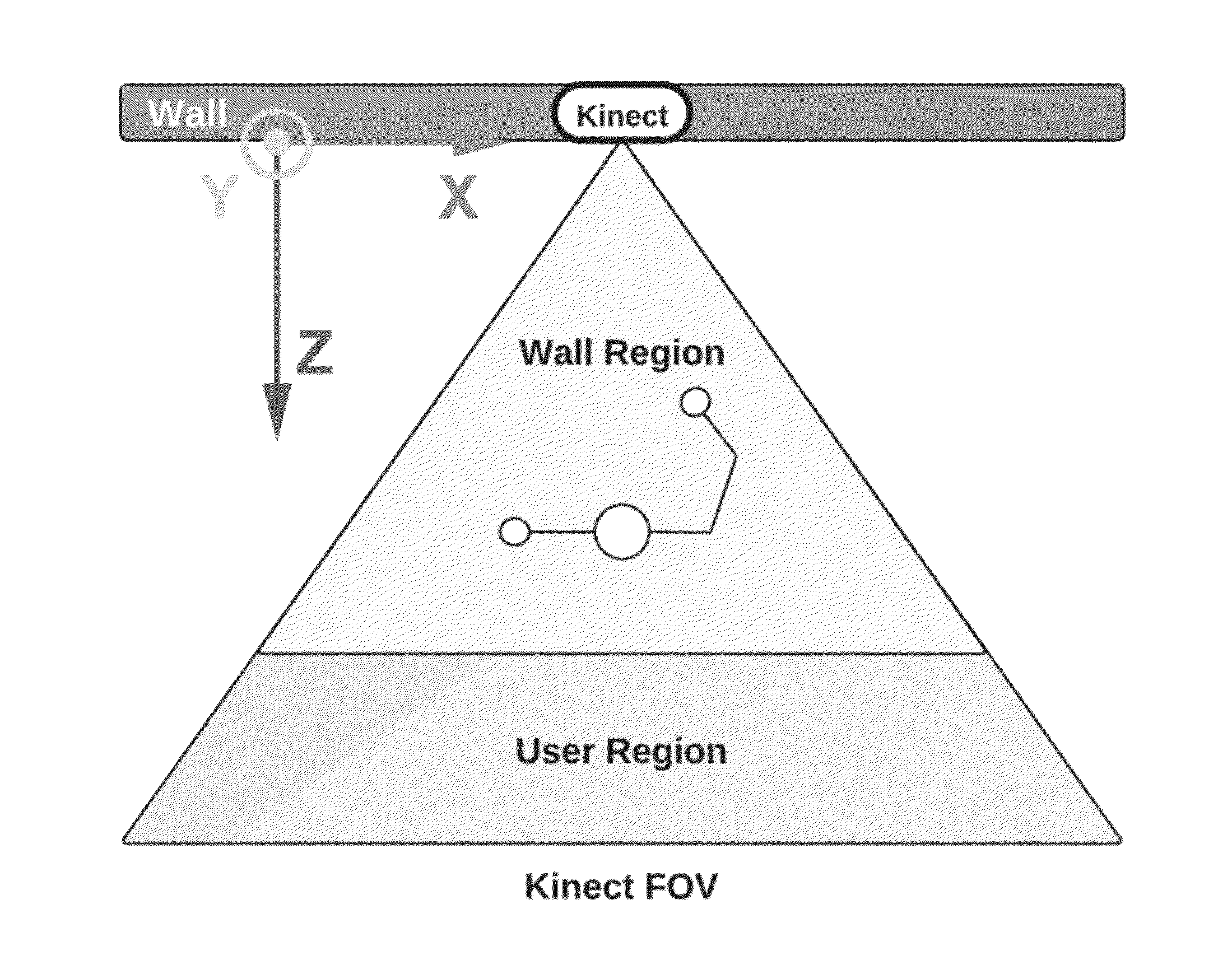
The present invention provides a method and system for providing three-dimensional interaction with a workspace displayed on a large-scale wall display. The system includes a camera and a computer programmed for capturing the user's movements and translating them into command signals to control a virtual tool. The virtual tool can be a tool to move, scale, rotate, create, delete, augment, or perform boolean operations on geometry. The programmed system can also include a holster attached directly to the user's avatar in the workspace for holding the virtual tool when not in use. The use of virtual tools and ease of access through proprioceptive cues and an actable makes the workspace more user-friendly and efficient for creating and managing geometry.

Problems solved by technology

The large size of wall displays and the relatively large working distance (how far the user stands or sits from the display), makes interaction with traditional WIMP (Windows Icon Menu Pointer) methods impractical, unless graphical widgets are scaled up, thus reducing the usefulness of the high resolution.
First, the mapping between the user and the 3D interface is more complex than for a 2D interface.
Second, the creation of geometry often requires more precise control, increased tool complexity and nuanced interaction than simply viewing existing geometry and data.
However, the large size of these displays prevents effective use of traditional 3D input methods for desktop applications.
This work, however, used hand-held devices for tracking and afforded only 2D input.

Method used


Image

  • Dockable Tool Framework for Interaction with Large Scale Wall Displays
  • Dockable Tool Framework for Interaction with Large Scale Wall Displays
  • Dockable Tool Framework for Interaction with Large Scale Wall Displays

Examples


Embodiment Construction

[0029]The presently disclosed subject matter now will be described more fully hereinafter with reference to the accompanying Drawings, in which some, but not all embodiments of the inventions are shown. Like numbers refer to like elements throughout. The presently disclosed subject matter may be embodied in many different forms and should not be construed as limited to the embodiments set forth herein; rather, these embodiments are provided so that this disclosure will satisfy applicable legal requirements. Indeed, many modifications and other embodiments of the presently disclosed subject matter set forth herein will come to mind to one skilled in the art to which the presently disclosed subject matter pertains having the benefit of the teachings presented in the foregoing descriptions and the associated Drawings. Therefore, it is to be understood that the presently disclosed subject matter is not to be limited to the specific embodiments disclosed and that modifications and other ...


PUM


Abstract

In accordance with an aspect of the present invention, a device and a method allows for body-based interaction with 3D applications on wall displays. The interface consists of virtual dockable tools which can be unholstered, used to manipulate geometry, and holstered on the user's body. The system also utilizes proprioceptive cues to allow the user to manipulate and holster tools without visual feedback. A 3D depth camera maps 3D user position to 3D coordinates in the virtual scene. Partitioning the physical work space into a region for interaction with geometry, and a region for tool management allows for intuitive mapping between the physical and virtual work space. The system can support multiple users, including simultaneous interaction with the environment, and tool exchange between users.

Description

CROSS REFERENCE TO RELATED APPLICATION[0001]This application claims the benefit of U.S. Provisional Patent Application No. 61 / 700,605, filed on Sep. 13, 2012, which is incorporated by reference herein in its entirety.GOVERNMENT SPONSORSHIP[0002]This invention was made with government support under NSF CPS-0931805 awarded by the National Science Foundation. The government has certain rights in the invention.FIELD OF THE INVENTION[0003]The present invention relates generally to computing. More particularly, the present invention relates to a tool framework for large scale displays.BACKGROUND OF THE INVENTION[0004]Most commonly, computing platforms include a screen sized for use on a personal desk or a laptop. A user can interact with these screens using a point-and-click type mouse, a touchpad, or a touchscreen. However, wall display are increasingly becoming a popular platform for computing, visualization, 2D and 3D manipulation, brainstorming, decreasing costs in display hardware su...

Claims


Application Information

Patent Timeline
IPC IPC(8): G06F3/0481G06F3/0482
CPCG06F3/0482G06F3/04815
Inventor GUERIN, KELLEHER RICCIOHAGER, GREGORY
Owner THE JOHN HOPKINS UNIV SCHOOL OF MEDICINE
Learn More