
Apparatus and method for display

a technology of display apparatus and display method, applied in the field of display apparatus and method, can solve the problems of inability to precisely detect objects, inability to obtain uniform depth value of 3d image conversion method, and inability to accurately detect objects, etc., to minimize the adjustment of estimated depth value and minimize time taken

Inactive Publication Date: 2014-03-06
SAMSUNG ELECTRONICS CO LTD
View PDF2 Cites 74 Cited by
  • Summary
  • Abstract
  • Description
  • Claims
  • Application Information

AI Technical Summary

Benefits of technology

The patent text describes a new method and device for displaying 3D images. The new device and method can more efficiently convert 2D images to 3D images, by allocating depth values to objects in the image frames more quickly and accurately. This reduces the time required for the process and also improves the quality of the depth value estimates. Overall, this technology can make it easier and faster for users to create and view 3D images.

Problems solved by technology

However, such conventional 3D image conversion methods cannot obtain the uniform depth value, or cannot precisely detect the object in each frame.
In addition, when adjusting the depth value estimated per object, the conventional 3D image conversion methods take much time to determine whether to adjust the corresponding depth value and to adjust the depth value according to the determination.

Method used


Image

  • Apparatus and method for display
  • Apparatus and method for display
  • Apparatus and method for display

Examples


Embodiment Construction

[0034]Reference will now be made in detail to embodiments, examples of which are illustrated in the accompanying drawings, wherein like reference numerals refer to the like elements throughout.

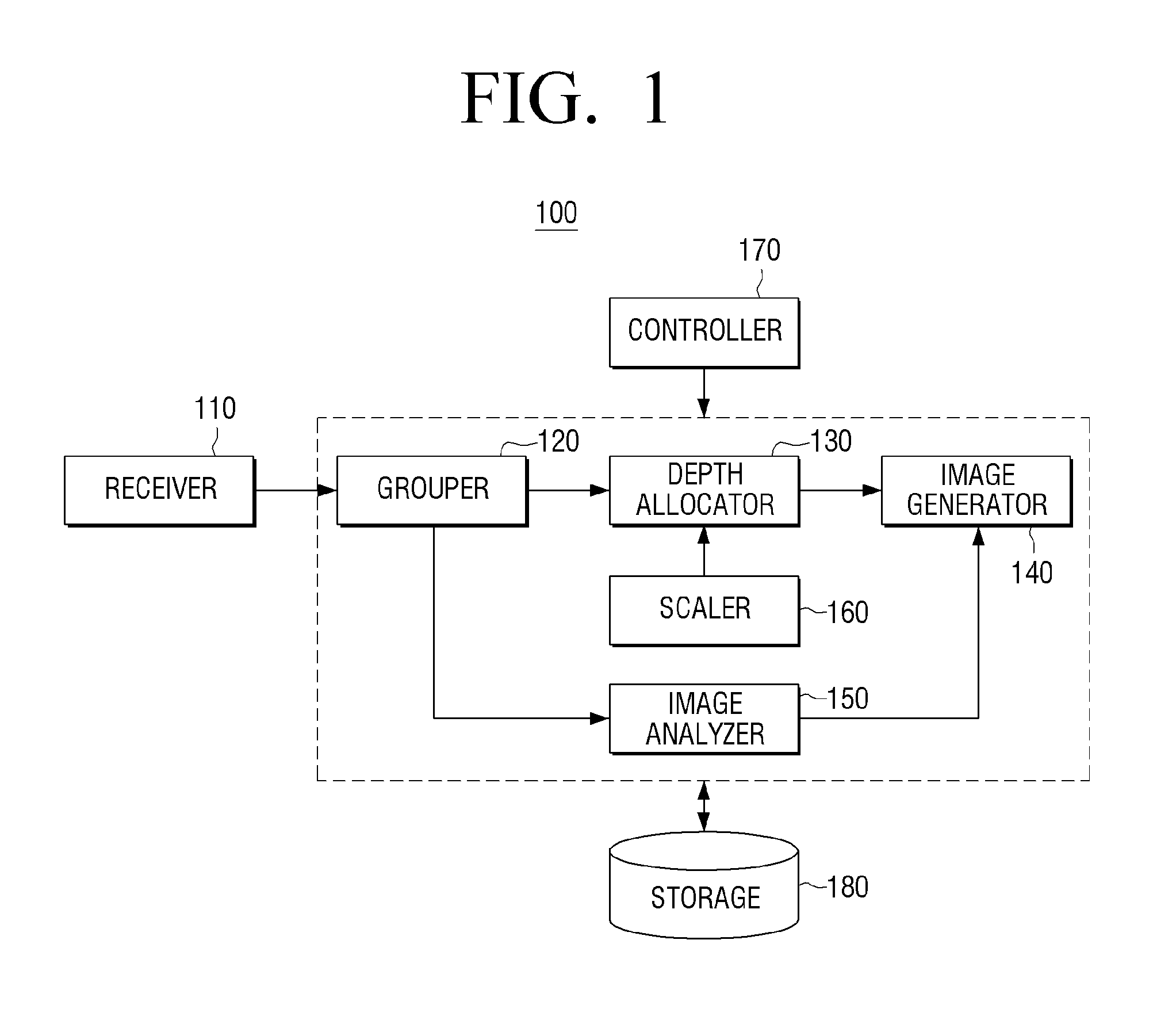
[0035]FIG. 1 is a block diagram of a display apparatus according to an embodiment.

[0036]As shown in FIG. 1, the display apparatus 100 includes a receiver 110, a grouper 120, a depth allocator 130, and an image generator 140. The receiver 110 for receiving an image can receive an image from a broadcasting station over a broadcasting network, or receive an image from a web server over Internet. When receiving the image from the broadcasting station over the broadcasting network, the receiver 110 can include a tuner (not shown), a demodulator (not shown), an equalizer (not shown), and so on. When receiving the image from the web server over the Internet, the receiver 110 can include a network interface (not shown). In addition, the receiver 110 can receive an image from various recording medium p...


PUM


Abstract

Display apparatus and method are provided. The display apparatus may include a receiver for receiving an image; a grouper for analyzing the received image and grouping a plurality of frames of the received image based on the analysis; a depth allocator for determining at least two key frames from a plurality of frames grouped into at least one group, and allocating a depth per object in the determined key frames; and an image generator for generating a 3D image corresponding to other frames excluding the key frames based on a depth value allocated to the key frames. Hence, the display apparatus can allocate the depth value of a higher quality to the object in the frames of the received image.

Description

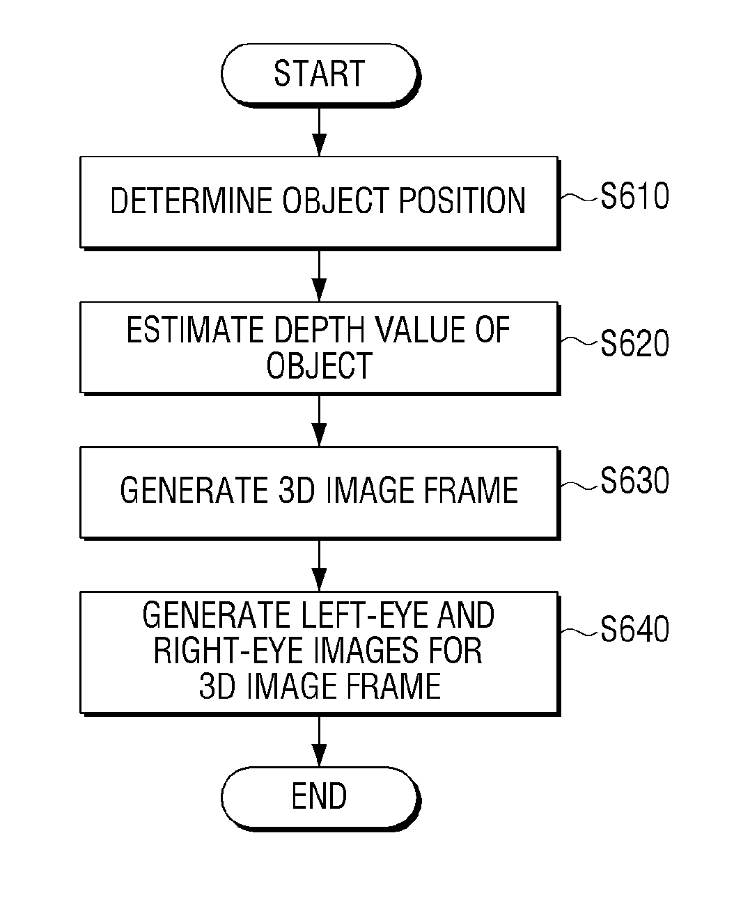
CROSS-REFERENCE TO RELATED APPLICATIONS[0001]This application claims the priority benefit under 35 U.S.C. §119 (a) from Korean Patent Application No. 10-2012-0097259 filed on Sep. 3, 2012 in the Korean Intellectual Property Office, the entire disclosure of which is incorporated herein by reference.BACKGROUND[0002]1. Field[0003]Embodiments relate generally to display apparatus and method. More particularly, embodiments relate to display apparatus and method for providing a 3D image.[0004]2. Description of the Related Art[0005]Conventional display devices convert a received image to a 3D image using one of the following methods.[0006]In general, upon receiving the image, the display device determines a depth value by analyzing the received image and creates 3D images for left-eye and right-eye images based on the determined depth value. Alternatively, the display device determines the depth value per object by analyzing frames of the received image and estimating an edge of the object...

Claims


Application Information

Patent Timeline
IPC IPC(8): G06T15/10
CPCG06T15/10H04N13/261H04N13/00
Inventor AHN, WON-SEOKHAN, SEUNG-HOON
Owner SAMSUNG ELECTRONICS CO LTD
Learn More