
Dental piezoelectric ultrasonic magnetic switching scaler handpiece and method of use

a piezoelectric ultrasonic and magnetic switching technology, applied in the field of dental tools, can solve the problems of inconvenient use, inconvenient use, and inability to access the switch at all, and achieve the effect of maintenance, reducing the cost of operation, and improving the efficiency of clinic operation

Inactive Publication Date: 2014-02-06
DENTAMERICA INC CALIFORNIA
View PDF9 Cites 2 Cited by
  • Summary
  • Abstract
  • Description
  • Claims
  • Application Information

AI Technical Summary

Benefits of technology

The present invention is about a dental scaler handpiece that uses magnetic technology to turn on and off. It is designed to prevent magnetic interference and can be used by dentists and hygienists. The handpiece has a suspended movable activation magnet and a magnetically activated switch, making it easy to turn on and off. The activation magnet is unaffected by the user's position or the angle of the handpiece. The handpiece is convenient for both left and right handed users and offers equal performance regardless of the user's hands being in a certain position.

Problems solved by technology

However, hand controlled switches are not popular due to the limitations of ergonomics, the inability to be sterilized (autoclaved), and controllability.
A hand activated switch has the disadvantage that the switch is not accessible at all times as the handpiece is being manipulated during the course of a dental procedure.
Foot controlled switches also have drawbacks in a clinical setting.
A clinic floor with several competing devices for floor space is not an efficient approach to efficient clinic operation.
Foot pedals can also interfere with general cleaning routines of the dental office floor, as the foot pedals must be moved off the office floor to effect cleaning.
The cable can potentially tangle with the user during normal clinical procedures.
The constant risk of wire damage to the foot switch cable can make foot switch pedals a solution that is not optimal.
Even wireless foot switches have problems with interference that make them not a viable option in the marketplace.
Issues such as floor placement and positioning are still not resolved with wireless foot pedals.

Method used


Image

  • Dental piezoelectric ultrasonic magnetic switching scaler handpiece and method of use
  • Dental piezoelectric ultrasonic magnetic switching scaler handpiece and method of use
  • Dental piezoelectric ultrasonic magnetic switching scaler handpiece and method of use

Examples


Embodiment Construction

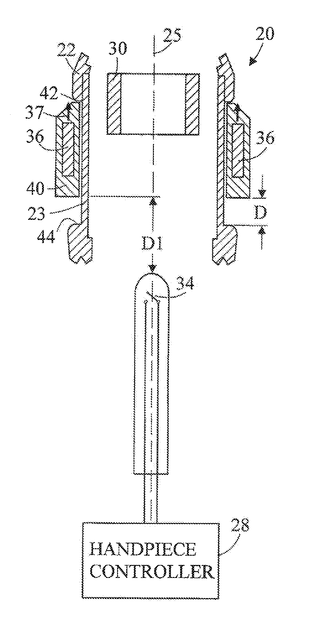
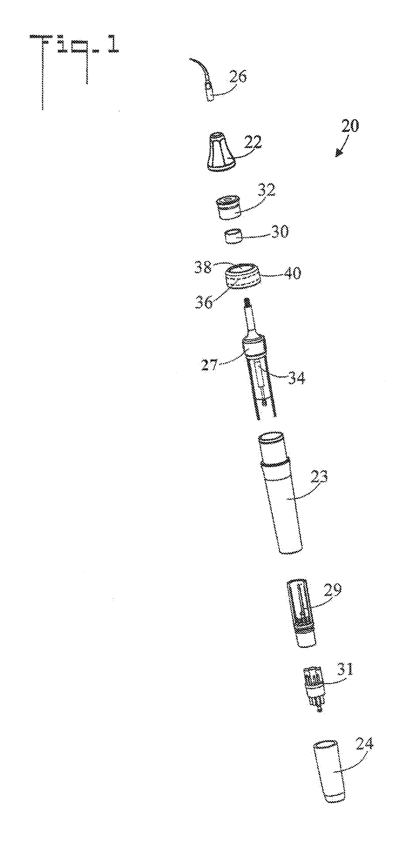
[0035]Referring initially to FIGS. 1-3, there are illustrated reduced exploded, side elevation, and cutaway side elevation views, respectively, of a dental piezoelectric ultrasonic magnetic switching scaler handpiece in a de-energized state, the dental scaler handpiece generally designated as 20. Dental scaler handpiece 20 includes a housing that has a longitudinal axis 25. In the shown embodiment, the housing comprises a front housing 22, a main housing 23, and a rear housing 24. An ultrasonic piezoelectric transducer 27 is located inside main housing 23. Front housing 22 receives a dental tool 26 that is coupled to the ultrasonic piezoelectric transducer 27. Rear housing 24 connects to an external power supply in a handpiece controller 28 (refer also to FIGS. 6 and 7). A fixed magnet 30 is disposed within the main housing 23. In the shown embodiment, fixed magnet 30 is surrounded by a fixed magnet housing 32. Magnetically activated switch 34 is spaced apart from fixed magnet 30 al...


PUM


Abstract

A dental piezoelectric ultrasonic magnetic switching scaler handpiece is activated by magnetic means. The dental piezoelectric scaler handpiece includes a housing that contains a fixed magnet and a magnetically activated switch. An activation magnet longitudinally slides along the outside of the housing from a de-energized position to an energized position. The activation magnet is biased to the de-energized position by the fixed magnet. When a user moves the activation magnet away from the fixed magnet and toward the magnetically activated switch, the magnetic field of the activation magnet activates the magnetically activated switch and turns the dental scaler handpiece on.

Description

TECHNICAL FIELD[0001]The present invention pertains generally to dental tools, and more particularly to a dental piezoelectric ultrasonic magnetic switching scaler handpiece that is activated by an activation magnet that externally surrounds the handpiece housing. The activation magnet is positionable to de-energized and energized positions along the longitudinal axis of the handpiece housing.BACKGROUND OF THE INVENTION[0002]Power driven dental tools are well known in the art. One such tool is an ultrasonic dental scaler that has a tip that vibrates at a high frequency in order to remove both plaque and calculus from teeth. Two types are available for producing the ultrasonic vibration: magnetostrictive and piezoelectric. The magnetostrictive type creates a pulsing magnetic field that is applied to a metal stack that flexes to move the tip. The piezoelectric type uses pulsing voltage that is applied to ceramic crystal that moves the tip.[0003]Ultrasonic scalers are typically control...

Claims


Application Information

Patent Timeline
Patent Type & Authority Applications(United States)
IPC IPC(8): A61C17/12
CPCA61C1/07A61C17/20
Inventor HUANG, JERRY T.
Owner DENTAMERICA INC CALIFORNIA
Learn More