
Comparator and relaxation oscillator employing same

a technology of oscillator and oscillator, applied in the direction of pulse manipulation, pulse technique, multiple input and output pulse circuits, etc., can solve the problems of inability to achieve the same frequency

Active Publication Date: 2014-01-30
NXP USA INC
View PDF13 Cites 6 Cited by
  • Summary
  • Abstract
  • Description
  • Claims
  • Application Information

AI Technical Summary

Benefits of technology

The present invention provides a comparator circuit that can generate clock signals for integrated circuits without using large quiescent currents. The comparator circuit uses a combination of comparators and relaxation oscillators to generate the clock signals. The invention also includes improvements to the comparators to reduce delays and improve accuracy. The technical effects of the invention include reducing delays in generating clock signals and improving accuracy without using large quiescent currents.

Problems solved by technology

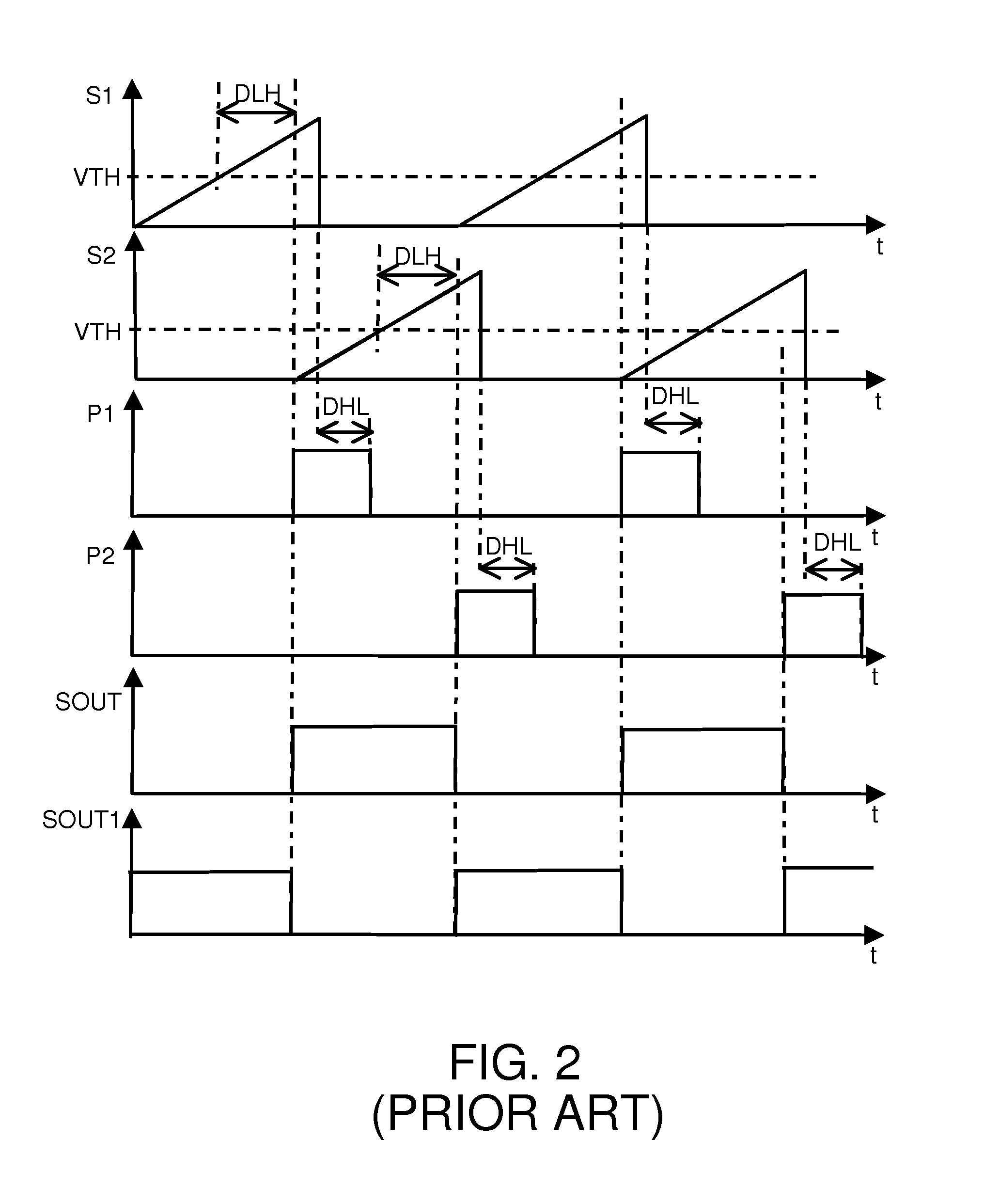
However, comparators have inherent low to high and high to low transition delays that can affect the upper limits and accuracy of the frequency of the oscillator circuit.
Furthermore, such inherent transition delays are undesirable for comparator circuits that require a rapid response time.
However, such rapid response times are obtained at the expense of relatively large and undesirable quiescent currents that flow through either or both pull up and pull down transistors.

Method used


Image

  • Comparator and relaxation oscillator employing same
  • Comparator and relaxation oscillator employing same
  • Comparator and relaxation oscillator employing same

Examples


Embodiment Construction

[0012]The detailed description set forth below in connection with the appended drawings is intended as a description of presently preferred embodiments of the invention, and is not intended to represent the only forms in which the present invention may be practiced. It is to be understood that the same or equivalent functions may be accomplished by different embodiments that are intended to be encompassed within the spirit and scope of the invention. In the drawings, like numerals are used to indicate like elements throughout. Furthermore, the terms “comprises,”“comprising,” or any other variation thereof, are intended to cover a non-exclusive inclusion, such that module, circuit, device components, method steps and structures that comprises a list of elements may include other elements not expressly listed or inherent to such module, circuit, steps or device components. Similarly, an element or step proceeded by “comprises” does not, without more constraints, preclude the existence...


PUM


Abstract

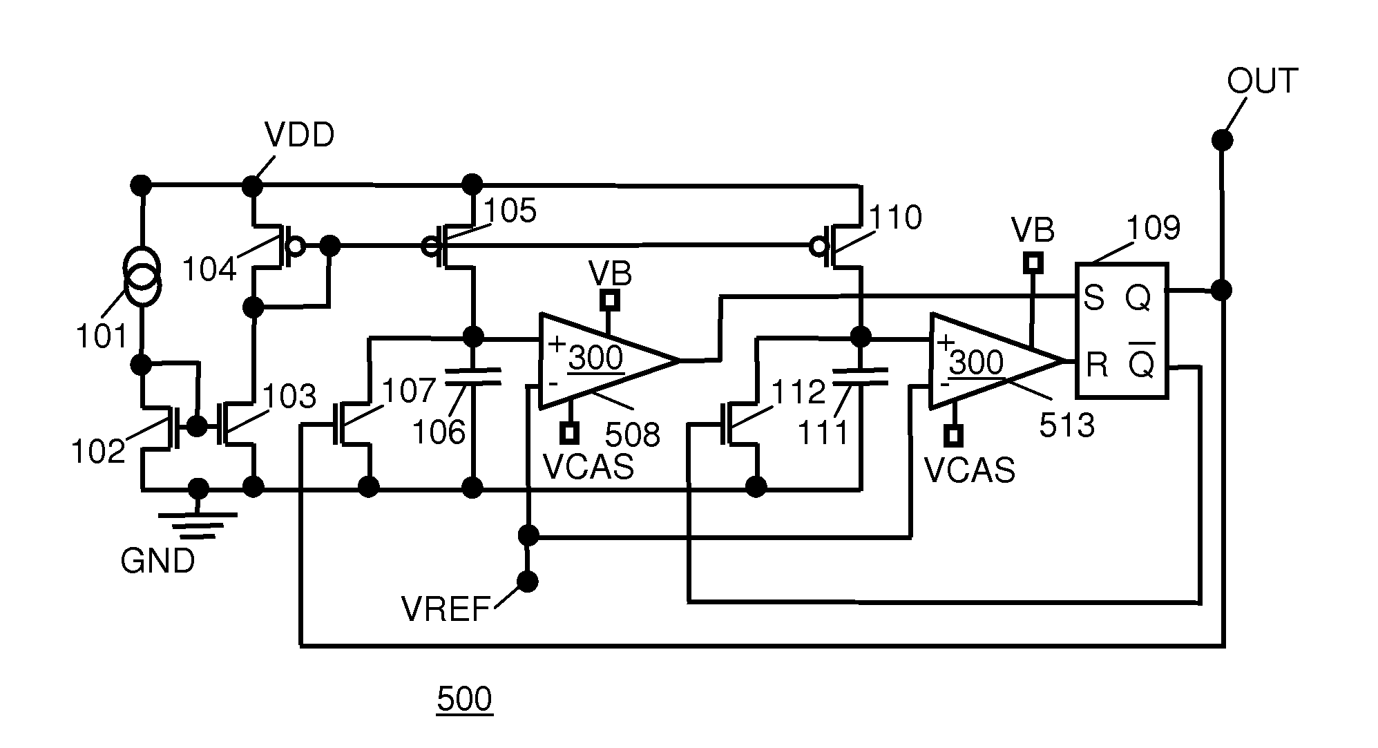
A relaxation oscillator has a comparator that includes first through third bias current transistors coupled to a first supply rail. First and second input transistors form a pair of parallel coupled transistors connected to the first bias current transistor. A first current mirror control transistor connects the first input transistor to a second supply rail. A first current mirror output transistor is coupled to the first current mirror control transistor, and connects the second bias current transistor to the second supply rail. A second current mirror control transistor connects the second input transistor to the second supply rail. A second current mirror output transistor is coupled to the second current mirror control transistor, and connects the third bias current transistor to the second supply rail. A transition time reduction transistor, coupled across the third bias current transistor, is coupled to the second bias current transistor, and provides a comparator output.

Description

BACKGROUND OF THE INVENTION[0001]The present invention relates to generation of clock signals for integrated circuits and, more particularly, to comparators and relaxation oscillators that use comparators.[0002]Relaxation oscillator circuits are found in many electronic circuit applications and are often used for generating clock signals that control the timing of such electronic circuits. For example, relaxation oscillator circuits can be used DC / DC converters, counters, shifting modules, microcontrollers and modulation circuitry. Typically, the period of the clock signal provided by a relaxation oscillator circuit is determined primarily by charging and discharging of two capacitors. Such charging and discharging is often controlled by current sources or current mirrors supplying charge currents to the capacitors and the discharging is effected by controlling transistors coupled across the capacitors.[0003]The charging and discharging of the capacitors typically provides ramp or s...

Claims


Application Information

Patent Timeline
IPC IPC(8): H03K5/22H03K3/353
CPCH03K3/0231H03K5/2472H03K3/02315H03K3/3545H03K4/502H03K5/2481H03K5/249
Inventor WANG, ZHENGXIANG
Owner NXP USA INC
Learn More