
Stapler

a stapler and stapler technology, applied in the field of staplers, can solve the problems of limited scope, narrow spacing, and tight fitting of the channel to the stapler, and achieve the effects of reducing the number of staplers

Inactive Publication Date: 2014-01-02
ISABERG RAPID
View PDF3 Cites 6 Cited by
  • Summary
  • Abstract
  • Description
  • Claims
  • Application Information

AI Technical Summary

Benefits of technology

The present invention proposes a stapler with a pivotable channel that has a connected sleeve for easy movement. The invention also includes a spindle that rotates and has a non-circular cross-section. The angle between the direction of movement of the clipping arrangement and the longitudinal direction of the channel changes depending on where in the movement the clipping arrangement is. Overall, the invention solves previous stapler issues and provides improved performance.

Problems solved by technology

The disadvantage of these earlier staplers is that the channel is fitted firmly to the stapler.
This means that the potential choices for placing the stapler relative to the horizontal plane are limited.
However, all previous staplers provide a solution with limited scope for placing the stapler at varying angles of inclination relative to the horizontal plane while at the same time ensuring reliable conveying of the leg clippings to the container.

Method used


Image

  • Stapler
  • Stapler
  • Stapler

Examples


Embodiment Construction

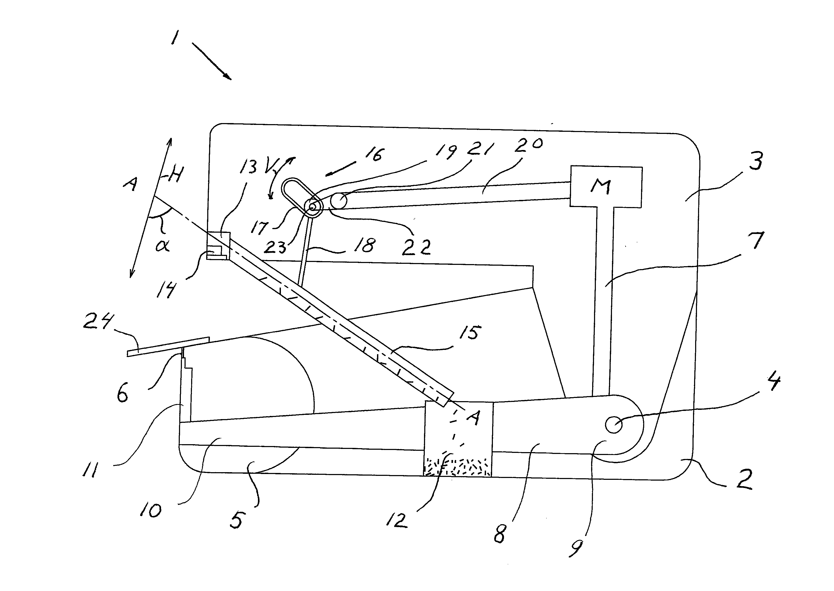
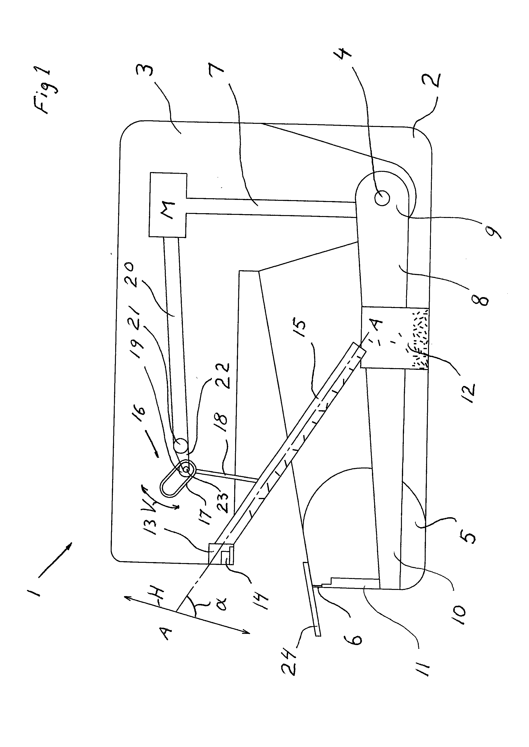
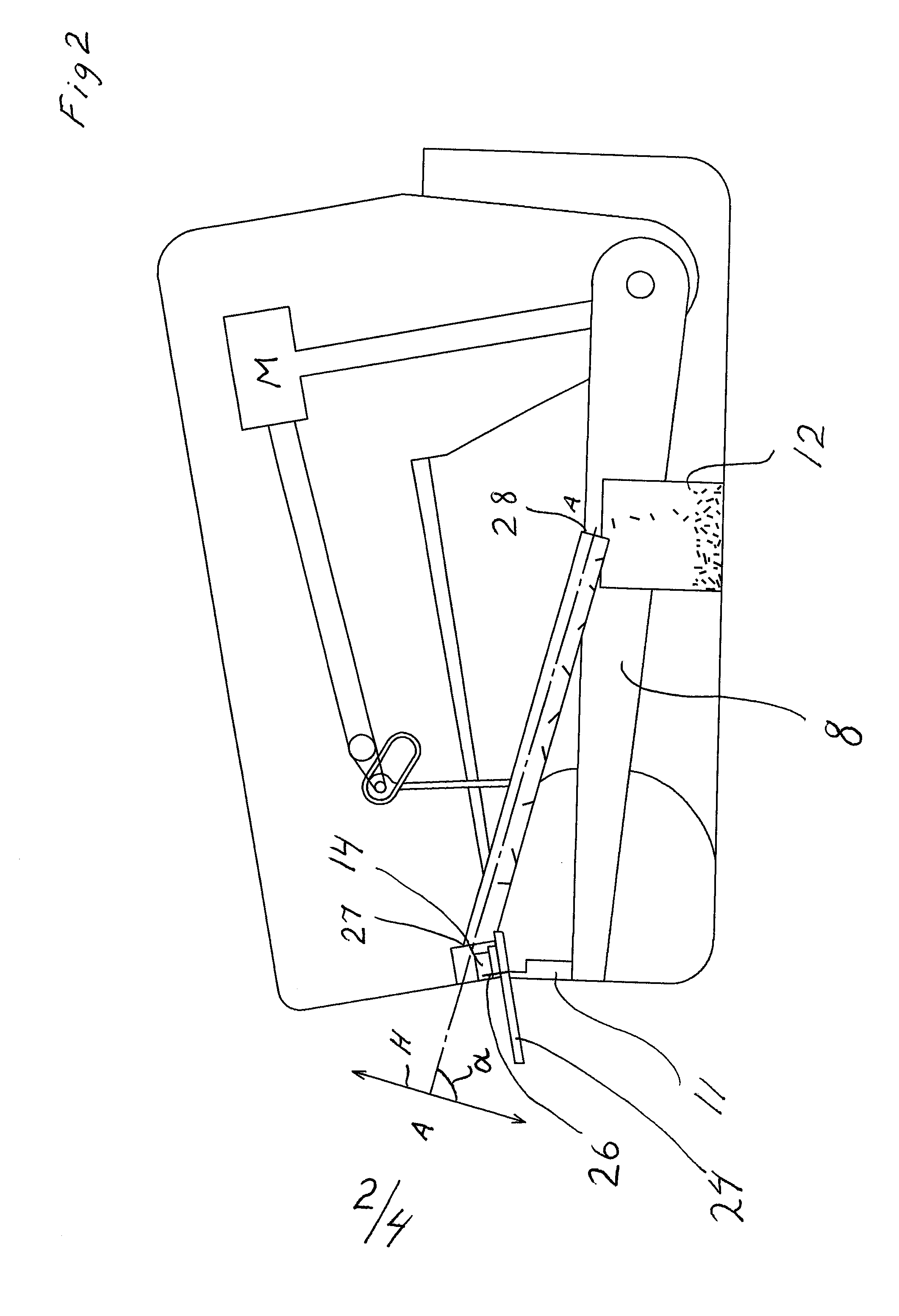
[0017]FIG. 1 depicts very schematically a stapler 1 which comprises the present invention. It only shows clearly those parts which are necessary for proper understanding of the invention. Parts and solutions which are obvious to specialists are only schematically depicted. In the figure the stapler is in a position of rest and the figure discloses that the stapler comprises a lower element 2 and an upper element 3 which are pivotably connected to one another by a spindle 4. In the lower element 2 there is a staple magazine 5 accommodating staples which are not visible in the drawing other than a schematically depicted staple 6 which is in its driving position. In the upper element 3 there is a motor M actively connected by a link arrangement 7 to a lever arm 8 which has a first end 9 connected pivotably to the spindle 4. The lever arm 8 has its opposite end 10 to the first end 9 connected to a driver 11 which is situated in or close to the magazine 5. In the lower element there is a...


PUM


Abstract

Stapler (1) for using a staple (6) to staple together a workpiece (24), e.g. a sheaf of papers, by the staple being driven through the workpiece, by a driver (11) fitted in the stapler, from a staple magazine (5) to a position in which the staple legs penetrate the workpiece, which stapler comprises also a clipping arrangement (14), which moves reciprocatingly relative to the staple magazine in a defined direction (H) between a working position and a position of rest so that the clipping arrangement in the working position clips off surplus lengths of the staple legs when they have penetrated the workpiece, and a container (12) for gathering the staple leg clippings by their being conveyed via a channel (15) which runs in a defined longitudinal direction (A-A) between the clipping arrangement and the container, which channel (15) is attached pivotably to the stapler by means of a connecting device (16).

Description

TECHNICAL FIELD[0001]The present invention relates to a stapler for using a staple which comprises a crown portion and, angled thereto, staple legs, to staple together a workpiece, e.g. a sheaf of papers, by the staple being driven through the workpiece, by a driver fitted in the stapler, from a staple magazine to a position in which the staple legs penetrate the workpiece, which stapler comprises also an anvil portion equipped with a clipping arrangement, which anvil portion and clipping arrangement move reciprocatingly relative to the staple magazine in a defined direction between a working position and a position of rest so that the clipping arrangement in the working position clips off surplus lengths of the staple legs when they have penetrated the workpiece, and a container for gathering the staple leg clippings by their being conveyed via a channel which runs in a defined longitudinal direction between the clipping arrangement and the container.STATE OF THE ART[0002]Staplers ...

Claims


Application Information

Patent Timeline
IPC IPC(8): B27F7/17
CPCB27F7/17B27F7/21B25C5/0207B25C5/00
Inventor STRAAT, OLLE
Owner ISABERG RAPID
Learn More