
System and method for attaching soft tissue to bone

a soft tissue and bone technology, applied in the field of bone anchors, can solve the problems of low pull-out strength, prolonged pain and recovery time, and loss of the ability to elevate and externally rotate the arm

Active Publication Date: 2013-12-19
CONMED CORP
View PDF4 Cites 45 Cited by
  • Summary
  • Abstract
  • Description
  • Claims
  • Application Information

AI Technical Summary

Benefits of technology

The system enhances suture anchor stability, simplifies surgical procedures, reduces recovery time, and improves the ease of handling during arthroscopic repairs by providing strong and secure attachment of soft tissue to bone with reduced surgical complexity.

Problems solved by technology

One common example is a torn rotator cuff, where the supraspinatus tendon has separated from the humerus causing pain and loss of ability to elevate and externally rotate the arm.
Such large incision procedures are traumatic, causing prolonged pain and recovery time.
However, many of these devices suffer from low pull-out strength, a lack of adequate suture attachment sites, a requirement to tie complicated knots with the sutures, complicated threading routines, a failure to assist the surgeon in positioning soft tissue into contact with bone prior to suturing to maximize bonding of the soft tissue to bone, and an overall difficulty in physically handling the devices during surgery.
Generally, injury to joints such as the shoulder and knee involve the tearing or separation of ligaments from their natural position on the bone.
The injury leads to a chronic instability in the joint which requires surgical intervention.
However, it is difficult to manipulate sutures within the surgical site using arthroscopic techniques.
In some techniques, such as knot tying, it is difficult to properly adjust the tension of the suture while tightening the knot.

Method used


Image

  • System and method for attaching soft tissue to bone
  • System and method for attaching soft tissue to bone
  • System and method for attaching soft tissue to bone

Examples


Embodiment Construction

[0109]Various embodiments include an anchor that can be inserted into bone and to which sutures can be attached. In one embodiment, the anchor comprises expandable tines that secure the anchor in bone after insertion. In some embodiments, a spreader is provided that can be used to expand the tines. Some embodiments include one or more suture lengths that are pre-attached to the spreader.

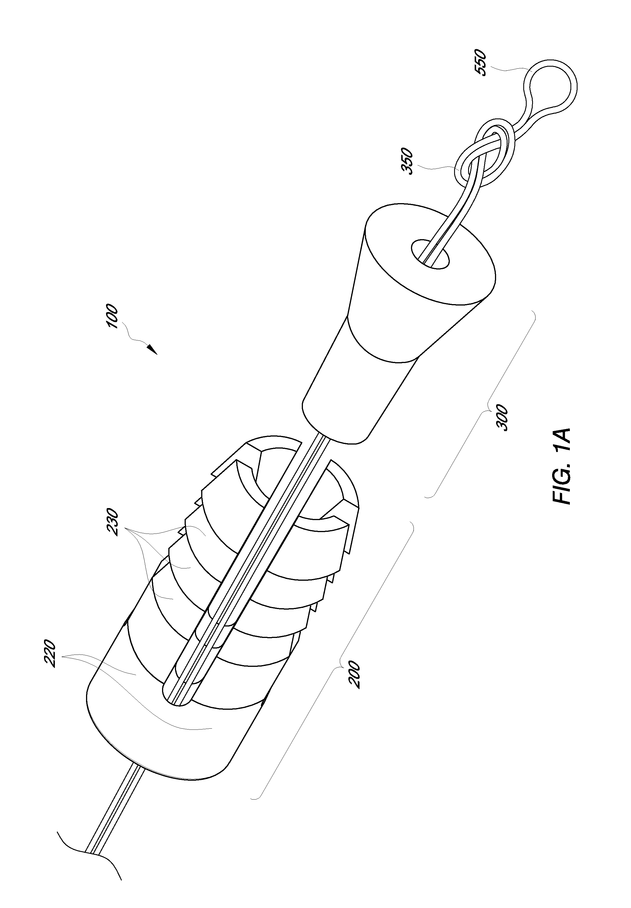
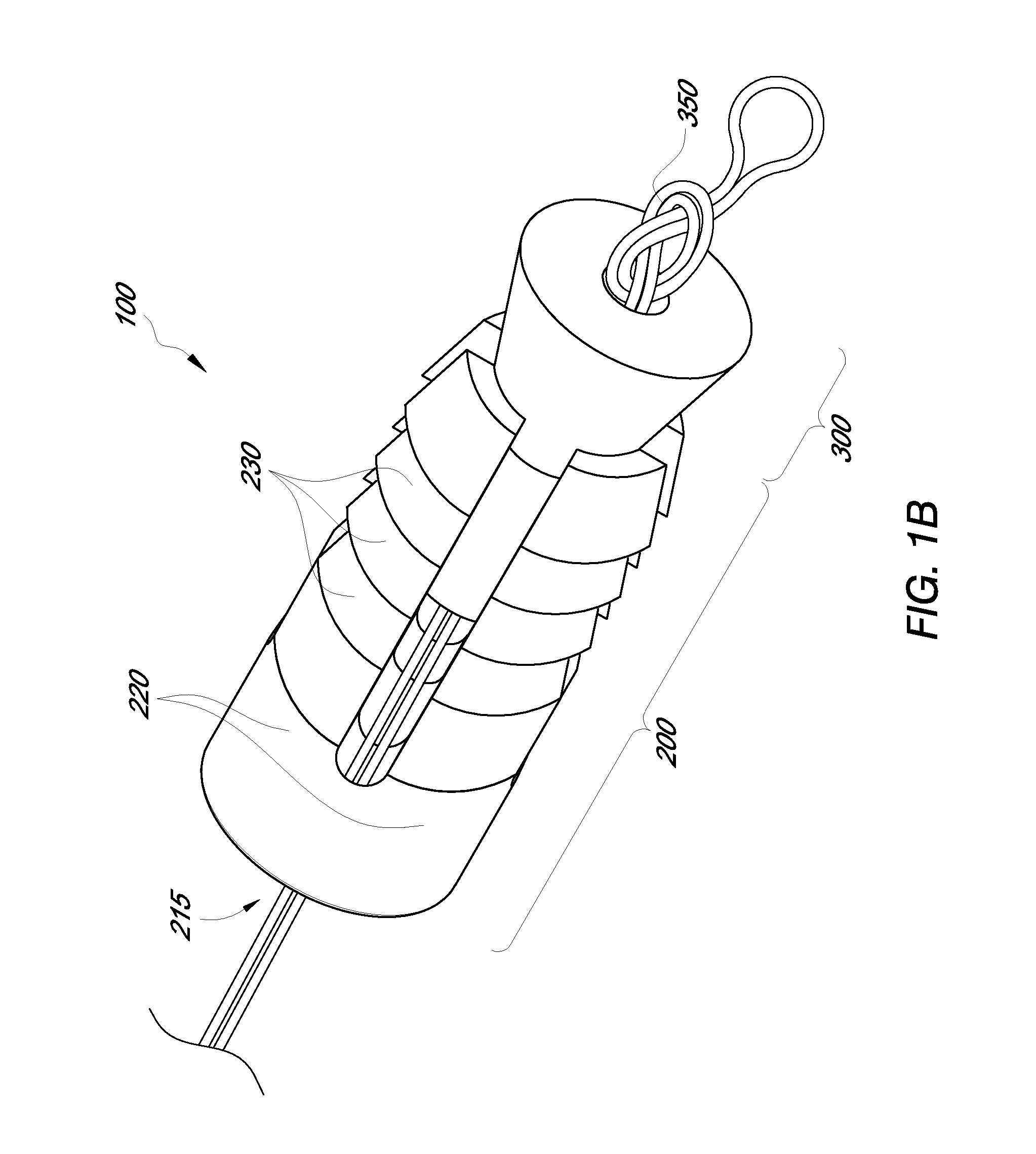
[0110]In various embodiments, soft tissue may be attached to bone utilizing one or more suture anchors. FIG. 1A depicts a side perspective view of a suture anchor 100 comprising an anchor body 200 and a spreader 300. The anchor body 200 is comprised of tines 220 and teeth 230. The tines 220 expand from the distal end of the anchor body 200 when the spreader 300 is engaged with the anchor body 200. The proximal end of the spreader 300 is configured to fit into the distal end of the anchor body 200. In FIG. 1A, the suture anchor 100 is in the undeployed, or unexpanded position. A suture loop 550 extend...


PUM


Abstract

Disclosed herein are methods and devices for securing soft tissue to a rigid material such as bone. A bone anchor is described that comprises an anchor body with expandable tines and a spreader that expands the tines into bone. Also disclosed is a bone anchor that comprises a base and a top such that suture material may be attached to apertures in the anchor top or else compressed between surfaces on the base and top to secure the suture to the anchor. Also described is an inserter that can be used to insert the bone anchor into bone and move the spreader relative to the anchor body attach suture material. Also described is an inserter that can be used to insert the bone anchor into bone and move the anchor top relative to the anchor body or anchor base to attach to or clamp suture material there between. Methods are described that allow use of single bone anchor to secure tissue to bone or also to use more than one bone anchor to provide multiple lengths of suture material to compress a large area of soft tissue against bone.

Description

RELATED APPLICATIONS[0001]This application is a continuation of U.S. application Ser. No. 12 / 697,138, filed Jan. 29, 2010, which claims the benefit of U.S. Provisional Application No. 61 / 148,805, filed Jan. 30, 2009, and 61 / 251,199, filed Oct. 13, 2009, each of which is herein incorporated by reference in its entirety.BACKGROUND[0002]1. Field of the Invention[0003]The present invention relates to medical devices. Some embodiments relate to a bone anchor for securing body tissue to bone.[0004]2. Description of the Related Art[0005]There are several medical procedures where a surgeon needs to attach soft tissue such as tendons or other soft connective tissue to bone. One common example is a torn rotator cuff, where the supraspinatus tendon has separated from the humerus causing pain and loss of ability to elevate and externally rotate the arm. To repair a torn rotator cuff, typically a surgical procedure is used to suture the torn tendon to the bone using a variety of methods. Some pr...

Claims


Application Information

Patent Timeline
Patent Type & Authority Applications(United States)
IPC IPC(8): A61B17/04
CPCA61B17/0401A61B2017/0409A61B2017/0424
Inventor HEAVEN, MALCOLMSIRIVONG, MIKXAYPRETTI, RUDYKO, MICHAELGREELIS, JOHN P.
Owner CONMED CORP
Learn More