
Real time safety systems

a real-time safety and system technology, applied in the field of real-time safety systems, can solve the problems of increasing complexity, increasing risk, and difficult management of hazards on plants and construction sites

Inactive Publication Date: 2013-12-19
FLUOR TECH CORP
View PDF4 Cites 17 Cited by
  • Summary
  • Abstract
  • Description
  • Claims
  • Application Information

AI Technical Summary

Benefits of technology

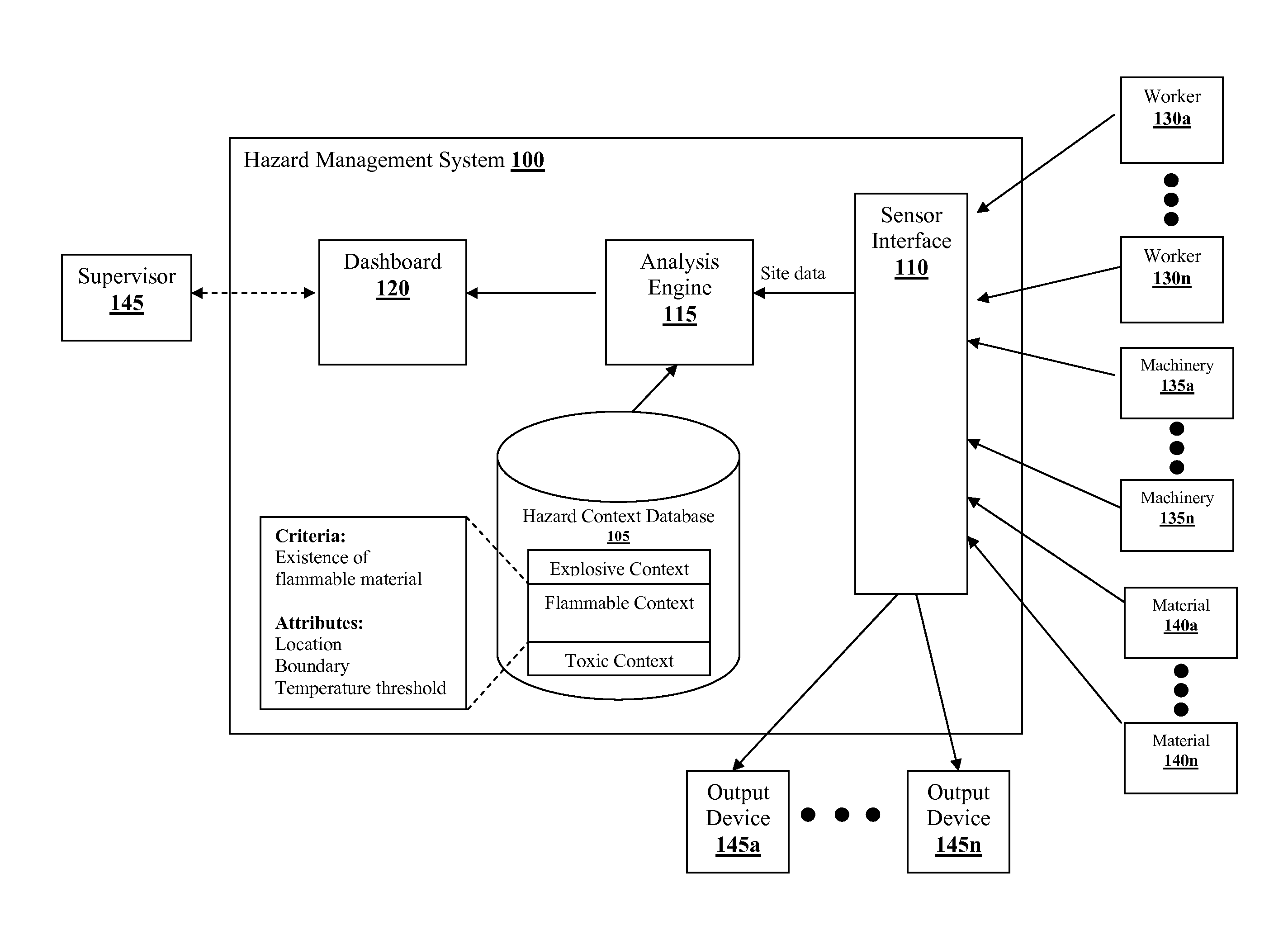
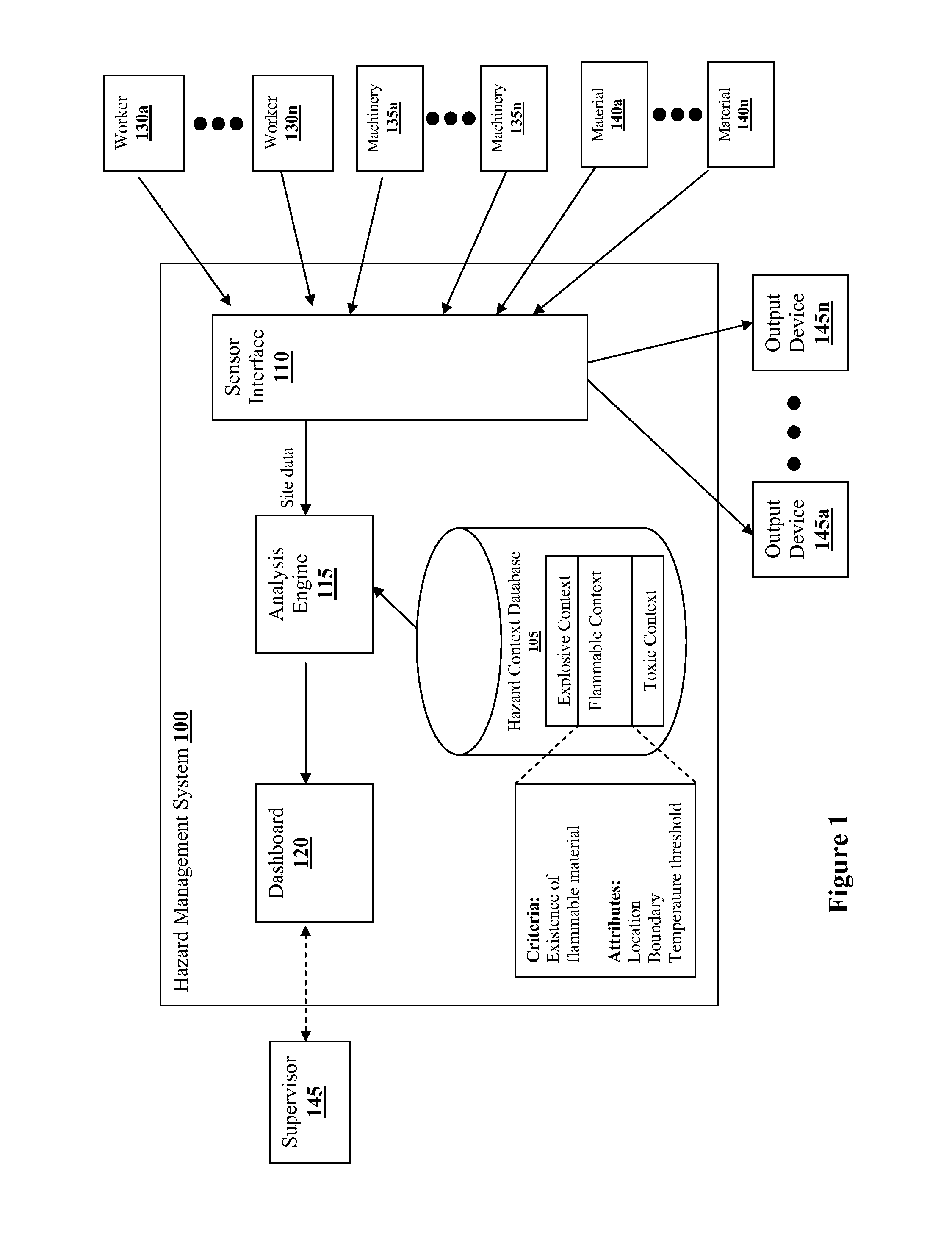
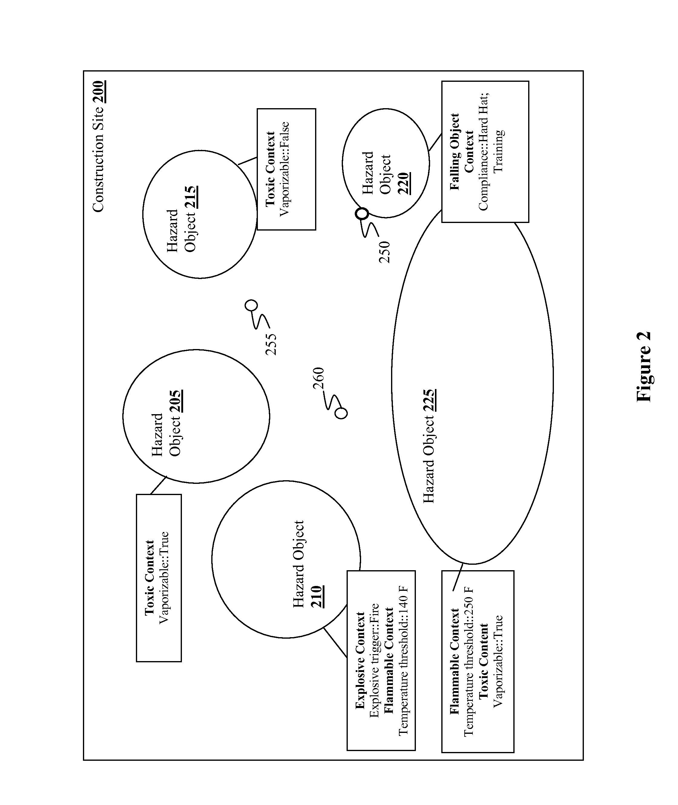
The patent describes a system for managing hazards in construction projects. The system includes a database of hazard contexts, a sensor interface, and an analysis engine. The analysis engine uses the sensor data to identify hazard objects and their associated hazard attributes. The system can then update these hazard attributes based on new sensor data and the hazard contexts. The analysis engine can also generate hazard notification criteria based on the hazard attributes and the attributes of workers on the construction site. The system can also log a history of hazard objects and alerts when hazard conditions exceed a threshold. Overall, the system helps to identify and manage hazards in construction projects to improve safety on the construction site.

Problems solved by technology

Hazards in plants and construction sites are often difficult to manage.
The size of these plants and construction sites and the dynamic nature of the hazards add to the complexities.
For example, an area in a construction site may appear to be safe at a moment but becomes hazardous in the next moment when heavy machineries or toxic materials are moved to the area.
In another example, the hazardous level of a building construction site may vary over time as different hazardous conditions exist at different stages of the construction.
However, none of the systems effectively deal with the dynamic nature of hazards in the constructions sites.

Method used


Image

  • Real time safety systems
  • Real time safety systems
  • Real time safety systems

Examples


Embodiment Construction

[0021]The following discussion provides many example embodiments of the inventive subject matter. Although each embodiment represents a single combination of inventive elements, the inventive subject matter is considered to include all possible combinations of the disclosed elements. Thus if one embodiment comprises elements A, B, and C, and a second embodiment comprises elements B and D, then the inventive subject matter is also considered to include other remaining combinations of A, B, C, or D, even if not explicitly disclosed.

[0022]It should be noted that while the following description is drawn to a computer / server based hazard management system, various alternative configurations are also deemed suitable and may employ various computing devices including servers, interfaces, systems, databases, agents, peers, engines, controllers, or other types of computing devices operating individually or collectively. One should appreciate the computing devices comprise a processor configu...


PUM


Abstract

A system for managing hazards in a construction site is presented. One aspect of the inventive subject matter includes a hazard management system comprising a hazard context database, a sensor interface, and a hazard analysis engine. The sensor interface is configured to acquire a site data feed that is representative of a construction site. The hazard analysis engine is configured to (i) instantiate a hazard object by comparing the site data feed to hazard criteria of the plurality of hazard contexts, (ii) update the hazard object based on the site data feed, (iii) generate hazard notification criteria related to the hazard object, (iv) obtain worker attributes from the site data, and (v) transmit a hazard notification to an output device when the worker attributes cause satisfaction of the hazard notification criteria.

Description

FIELD OF THE INVENTION[0001]The field of the invention is the management of construction hazards.BACKGROUND[0002]Hazards in plants and construction sites are often difficult to manage. The size of these plants and construction sites and the dynamic nature of the hazards add to the complexities. For example, an area in a construction site may appear to be safe at a moment but becomes hazardous in the next moment when heavy machineries or toxic materials are moved to the area. In another example, the hazardous level of a building construction site may vary over time as different hazardous conditions exist at different stages of the construction.[0003]Various systems and methods have been suggested for managing construction sites. For example, U.S. patent application publication 2007 / 0027732 to Hudgens (published in February, 2007) proposes a system that stores geographical locations of different hazards in a construction site and generates alerts to workers when they are in proximity ...

Claims


Application Information

Patent Timeline
IPC IPC(8): G08B21/00
CPCG06Q10/10G06Q50/08G08B21/02
Inventor PRIETO, ROBERT
Owner FLUOR TECH CORP
Learn More