
Magnetic Float Switch

Inactive Publication Date: 2013-12-12
PENTAIR FLOW TECH INC
View PDF6 Cites 8 Cited by
  • Summary
  • Abstract
  • Description
  • Claims
  • Application Information

AI Technical Summary

Benefits of technology

The technical effect of this patent is to create a float switch that has fewer parts that can cause problems with its operation.

Problems solved by technology

However, increasingly stringent regulations regarding products containing mercury have caused the industry to begin a shift toward alternative solutions for the mercury float switch.
Although there are several design variations of mechanical float switches on the market, the general perception is that they lack the reliability of the mercury switch design due to a multitude of moving parts inside the float housing.
The moving parts can degrade operation by becoming misaligned, damaged due to impact in shipping and / or operation, corrode and cease to operate, become damaged due to electrical arcing and / or chattering, as well as many other failure modes.
Yet, in conventional configurations, the magnet is not adequately secured so as to avoid physical interaction with the float housing or other components of the switch.
This can lead to problems with residue buildup and / or floating debris, causing the interaction between the magnet and the switch to degrade and eventually fail.

Method used


Image

  • Magnetic Float Switch
  • Magnetic Float Switch
  • Magnetic Float Switch

Examples


Embodiment Construction

[0018]Before any embodiments of the invention are explained in detail, it is to be understood that the invention is not limited in its application to the details of construction and the arrangement of components set forth in the following description or illustrated in the following drawings. The invention is capable of other embodiments and of being practiced or of being carried out in various ways. Also, it is to be understood that the phraseology and terminology used herein is for the purpose of description and should not be regarded as limiting. The use of “including,”“comprising,” or “having” and variations thereof herein is meant to encompass the items listed thereafter and equivalents thereof as well as additional items. Unless specified or limited otherwise, the terms “mounted,”“connected,”“supported,” and “coupled” and variations thereof are used broadly and encompass both direct and indirect mountings, connections, supports, and couplings. Further, “connected” and “coupled”...


PUM


Abstract

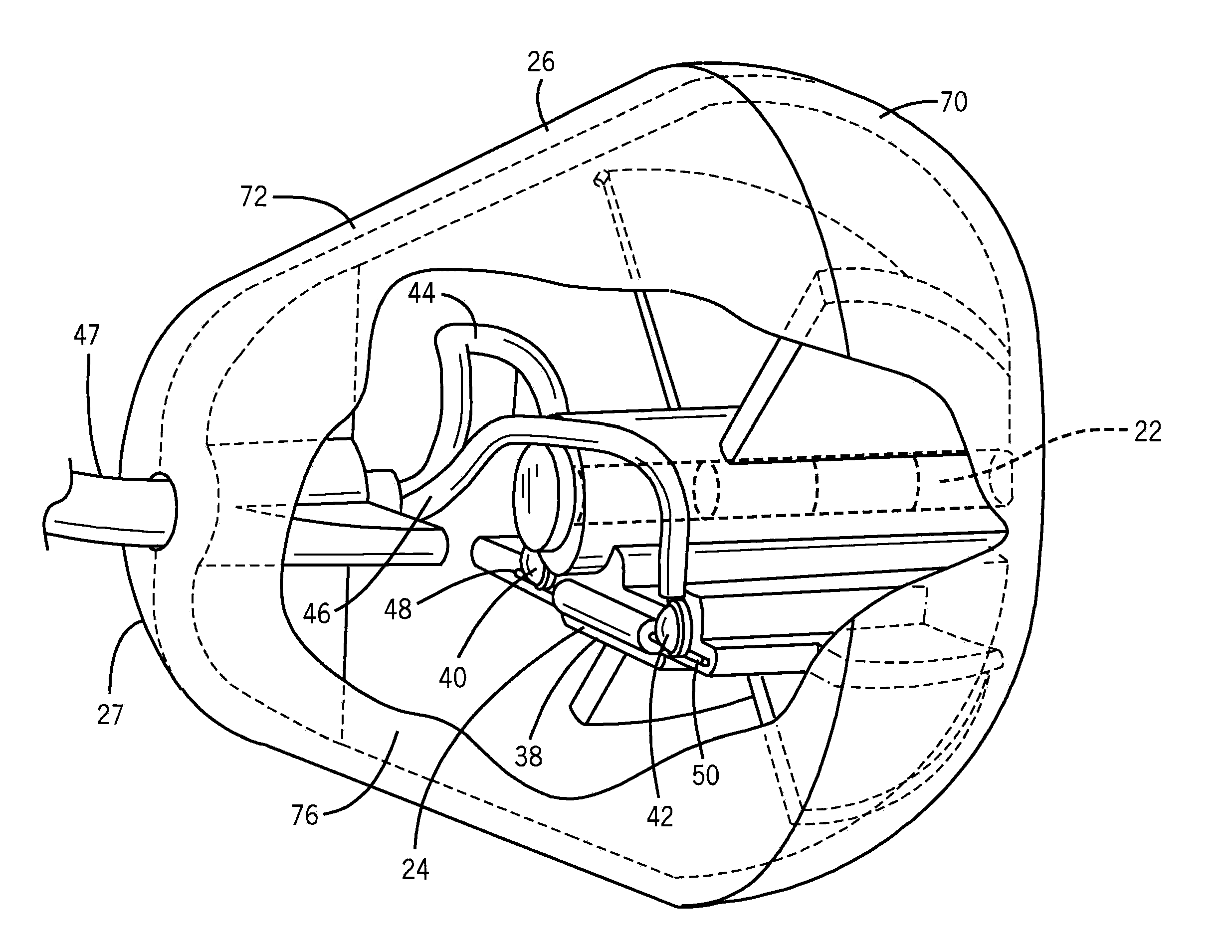
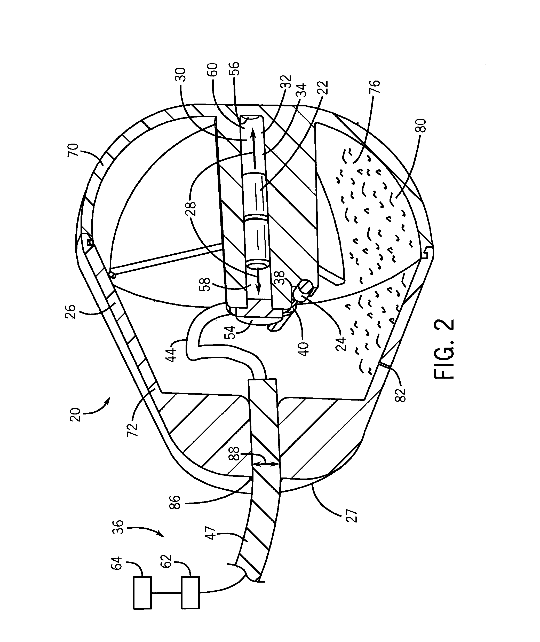
Embodiments of the invention provide a float switch with a float housing having a magnetically-activated, hermetically-sealed reed switch secured within an interior cavity in a first orientation and a permanent magnet positioned in a second orientation. The permanent magnet is movable within a chamber in the interior cavity between a first activation position and a second non-activation position. For connection to a pump, electrical conductors extend from the float housing at one end and are electrically coupled to the reed switch.

Description

BACKGROUND OF THE INVENTION[0001]Many conventional liquid pumps are directly or indirectly coupled to a switch or similar device that detects a liquid level in order to activate the pump when needed. Activation can include providing a signal to the pump to start or stop operation, and / or providing or removing power to the pump to start or stop the pump from operating. Activation can also include, for example, triggering alarms at pre-determined liquid levels of high and / or low level events.[0002]For many years, a common liquid level control switch consisted of a mercury switch embedded in a foam or plastic “float” housing. The fluctuating liquid level would cause the float to physically move, which would cause the mercury switch to close or open a circuit, depending on whether the mercury switch was normally open or normally closed. Mercury float switches were the industry standard due to their extreme reliability in harsh working environments. However, increasingly stringent regula...

Claims


Application Information

Patent Timeline
IPC IPC(8): H01H36/02
CPCH01H35/186G01F23/64G01F23/72G01F23/74G01F23/76H01H35/022H01H36/02
Inventor DAVIS, JASON JAMESROGERS, DOUGLAS RICHARDVALLEN, SHANE R.
Owner PENTAIR FLOW TECH INC
Learn More