
Storage Tank

Active Publication Date: 2013-12-12
2441050 ONTARIO LTD
View PDF3 Cites 0 Cited by
  • Summary
  • Abstract
  • Description
  • Claims
  • Application Information

AI Technical Summary

Benefits of technology

The patent text describes a system for connecting panels together using shear pegs and connector plates. The shear pegs are cylindrical pins that can be easily slid into panels with equal spacing between the pegs and holes. The pegs have smooth exterior surfaces to slide through the holes without any clamping action, and can be made from harder materials that are more resistant to shear. The connector plates can be inserted from the inside of the panels, and the ends of the panels can be secured in place to ensure proper alignment and functionality. The technical effects of this system include easier and more secure connection of panels, and improved durability and efficiency of the overall assembly.

Problems solved by technology

However these only contain very limited mounts so that a large number of such trailers would be necessary in many instances.
However as the requirement for the water is only temporary, it is necessary for the construction to be of a type which can be readily erected and quickly dismantled and removed to a new location.
However the requirement for rapid deployment of the temporary tank requires attention to an alternative for the high labor bolting system.

Method used


Image

  • Storage Tank
  • Storage Tank
  • Storage Tank

Examples


Embodiment Construction

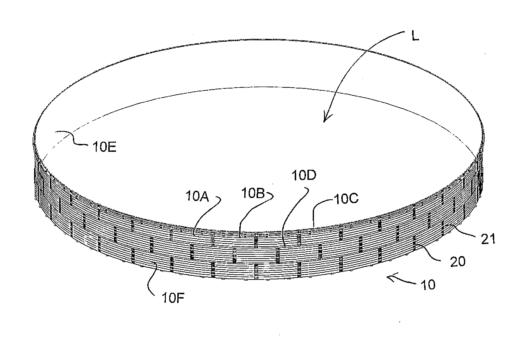
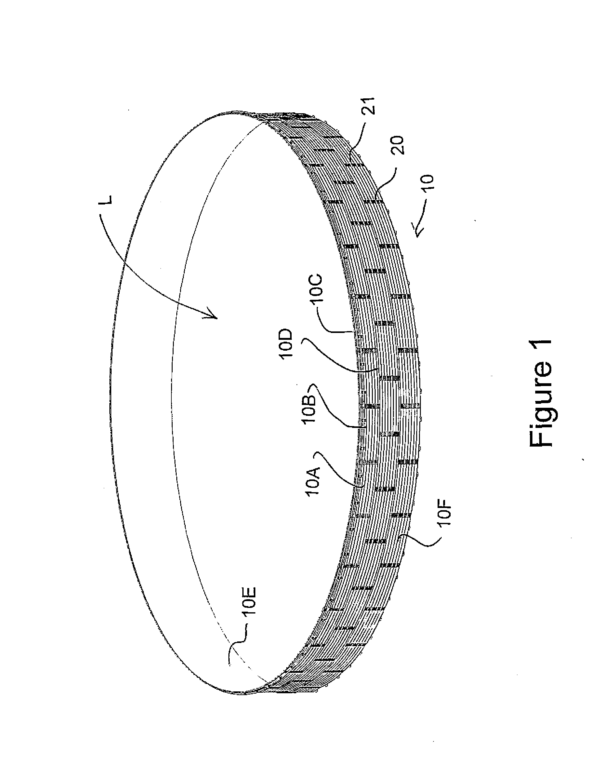
[0063]The arrangement shown in the drawings comprises a set of parts for assembly into a tank which in the figures are shown in the assembled position.

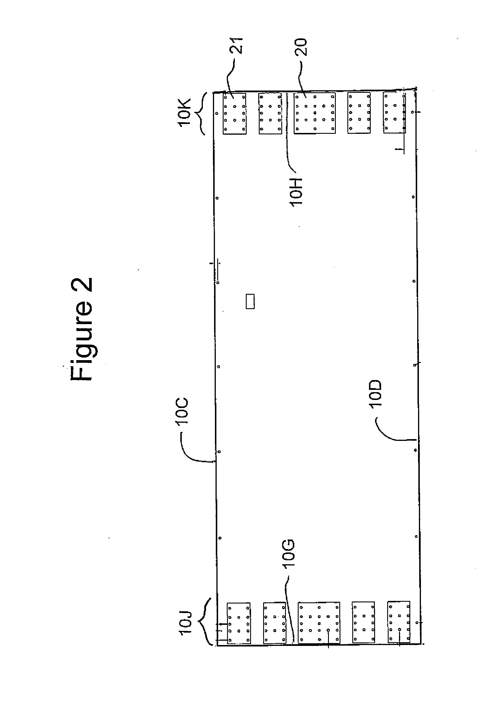
[0064]A peripheral wall 10 is formed by a plurality of panels 10A, 10B etc, each having a top edge 10C, a bottom edge 10D, an inner surface WE and an outer surface 10F.

[0065]Each panel has a first end 10G and a second end 10H such that the panels can be arranged with the first end of one connected to the second end of a second at an overlapping section 10J, 10K to form the complete peripheral wall surrounding an area to be confined.

[0066]The panels are formed from the same material used in grain bins so as to be horizontally corrugated for strength to form horizontal ribs 101 and valleys 102. The panels are of the same height so that the top edges 10C of a bottom or single row of the panels are arranged at a common height to define a common top edge of the peripheral wall with the bottom edge 10D resting on the ground.

[0067]Each panel...


PUM

PropertyMeasurementUnit
Pressureaaaaaaaaaa

Abstract

A liquid containment wall for a tank is formed by corrugated panels connected end to end and supported by upstanding brackets at spaced positions around the peripheral wall and a liner attached to the wall. Each panel has at each end an overlapping section with an array of aligned holes. The holes are connected by connector plates shaped and arranged to overlie a part of the array. Each plate has a plurality of shear pegs extending at right angles and at least one hole therethrough to receive a threaded bolt so that the bolt passes through a respective one of the aligned holes of the array to clamp the plate against the overlapping panels.

Description

[0001]This application claims the benefit under 35 USC 119 (e) of Provisional Application 61 / 648765 filed May 18, 2012.[0002]This invention relates to a storage tank which is designed particularly for temporary storage so that it can be erected quickly and easily, disassembled and moved to a new location for re-erection. Such tanks are commonly required for a high volume temporary supply of water for fractionation of underground rock in a process known colloquially as “fracking” with the water being contained in “frac-tanks”. However tanks for other purposes can also use this system.BACKGROUND OF THE INVENTION[0003]In order to make frac tanks completely portable, often they are mounted on trailers and many designs of this type are available. However these only contain very limited mounts so that a large number of such trailers would be necessary in many instances.[0004]Other tanks having a capacity between 2000 and 20,000 cubic meters are fabricated on site from panels, typically of...

Claims


Application Information

Patent Timeline
IPC IPC(8): B65D90/02
CPCB65D90/023E04H7/06Y10T29/49815E04H7/00B23P11/00B65D90/024B65D90/026B65D90/046B65D90/047
Inventor ALLEN, BRUCESHAN, YUQINWARNER, BRADMILLS, JAMES ANDREW
Owner 2441050 ONTARIO LTD
Learn More