Machine Vision Systems and Methods with Predictive Motion Control

a technology of machine vision and motion control, applied in the field of vision systems, can solve problems such as undesirable and troublesome encoders

Active Publication Date: 2013-11-28
COGNEX CORP
View PDF10 Cites 9 Cited by
  • Summary
  • Abstract
  • Description
  • Claims
  • Application Information

AI Technical Summary

Benefits of technology

[0008]Accordingly, some embodiments comprise a vision system for triggering an image acquisition of an object using motion data communicated from a motion controller on a network, the motion controller coupled to a motion drive. The vision system comprises a camera, with an acquisition controller coupled to the camera, the acquisition controller including a network interface, and the network interface operable to couple to the network. The camera, upon receiving motion data from the motion controller, uses a virtual axis application to plan the movement of a virtual axis for a motion cycle, the virtual axis allowing an acquisition trigger rate to be calculated by the camera that follows movement of the object caused by the motion drive. And, based on the calculated acquisition trigger rate, the camera generates an acquisition trigger signal for triggering the image acquisition of the object.

Problems solved by technology

However, encoders can be troublesome and undesirable due to their inaccuracies, noise immunity issues, and reliability issues.

Method used


Image

  • Machine Vision Systems and Methods with Predictive Motion Control
  • Machine Vision Systems and Methods with Predictive Motion Control
  • Machine Vision Systems and Methods with Predictive Motion Control

Examples


Embodiment Construction

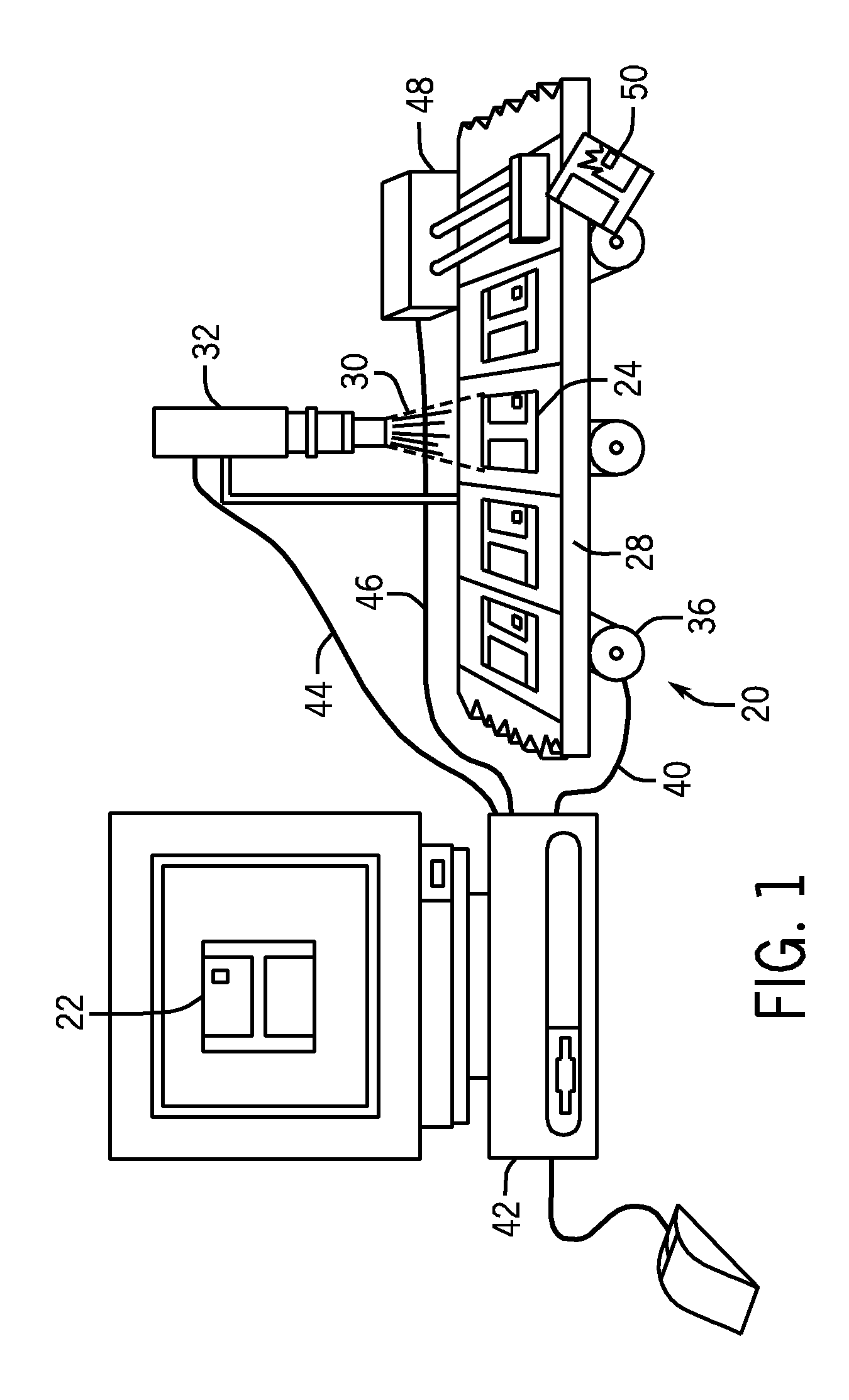
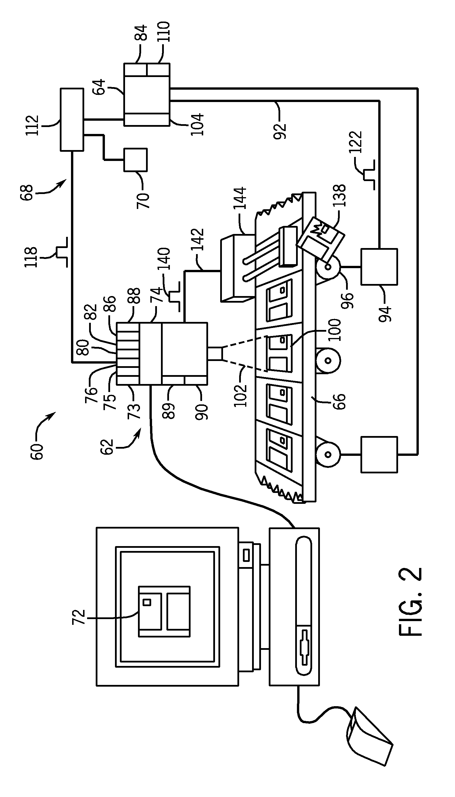
[0017]The various aspects of the subject invention are now described with reference to the annexed drawings, wherein like reference numerals correspond to similar elements throughout the several views. It should be understood, however, that the drawings and detailed description hereafter relating thereto are not intended to limit the claimed subject matter to the particular form disclosed. Rather, the intention is to cover all modifications, equivalents, and alternatives falling within the spirit and scope of the claimed subject matter.

[0018]As used herein, the terms “component,”“system” and the like are intended to refer to a computer-related entity, either hardware, a combination of hardware and software, software, or software in execution. For example, a component may be, but is not limited to being, a process running on a processor, a processor, an object, an executable, a thread of execution, a program, and / or a computer. By way of illustration, both an application running on a...


PUM


Abstract

Systems and methods trigger an image acquisition of an object using motion data communicated from a motion controller on a network, the motion controller coupled to a motion drive. A camera, upon receiving motion data from the motion controller, uses a virtual axis application to plan the movement of a virtual axis for a motion cycle, the virtual axis allowing an acquisition trigger rate to be calculated by the camera that follows movement of the object caused by the motion drive. Based on the calculated acquisition trigger rate, the camera generates an acquisition trigger signal for triggering the image acquisition of the object.

Description

CROSS-REFERENCE TO RELATED APPLICATIONS[0001]Not applicable.STATEMENT REGARDING FEDERALLY SPONSORED RESEARCH OR DEVELOPMENT[0002]Not applicable.BACKGROUND OF THE INVENTION[0003]The present invention relates to vision systems, and more specifically, to a vision system coupled to a motion controller, the motion controller providing motion data used for generating an image acquisition trigger signal.[0004]In many applications, machine vision or image processing analysis is used to inspect or locate an object. For example, in manufacturing applications, machine vision analysis may be used to detect defects in a manufactured object by acquiring images of the object and using various types of image processing algorithms to analyze the images. As an example, a system to manufacture an object such as a memory disk may use machine vision to examine the object in order to detect manufacturing defects, and ensure that the object is marked or assembled properly.[0005]In such machine vision syst...

Claims


Application Information

Patent Timeline
Patent Type & Authority Applications(United States)
IPC IPC(8): H04N5/232H04N7/18
CPCG01B11/04G01B11/24G03B15/16G01N21/8806H04N23/661H04N23/73
Inventor PETERSON, DALE
Owner COGNEX CORP
Why Eureka
Try Eureka