
Water flow electricity generating device

Inactive Publication Date: 2013-10-24
KAWASAKI HEAVY IND LTD
View PDF31 Cites 15 Cited by
  • Summary
  • Abstract
  • Description
  • Claims
  • Application Information

AI Technical Summary

Benefits of technology

The invention is a configuration for a rotor that reduces durability degradation and allows for the use of a water lubrication medium, which reduces device cost and improves maintenance. The rotor includes a float unit on one side that creates a buoyant force, which reduces the negative effects of gravity on the bearing. This results in a more stable and durable rotor.

Problems solved by technology

However, in order to perform the hydro-electric power generation, it is necessary to construct a dam that retains a water-level difference, a large amount of construction cost is required, and an environmental load also increases.

Method used


Image

  • Water flow electricity generating device
  • Water flow electricity generating device
  • Water flow electricity generating device

Examples


example

[0052]FIG. 9(a) is a graph illustrating a relationship between a flow rate and a torque and a relationship between the flow rate and a pitch angle in an example, and FIG. 9(b) is a graph illustrating a relationship between the flow rate and an output and a relationship between the flow rate and a rotating speed in that case. As illustrated in FIGS. 9(a) and 9(b), in the example, the pitch angle is controlled at a constant value of about 80 degrees such that the rotating blade 8 rotates easily in the low-speed range where the flow rate ranges from 0 to 1.5 m / s. Also, the pitch angle is controlled at a constant value of about 40 degrees (the rated flow rate of 4 m / s) such that torque generation efficiency (electricity generation efficiency) is improved in the normal range where the flow rate ranges from 1.5 to 4 m / s. Further, in the high-speed range where the flow rate ranges from 4 to 6 m / s, the variable control of the pitch angle is performed from about 40 to about 60 degrees such t...


PUM


Abstract

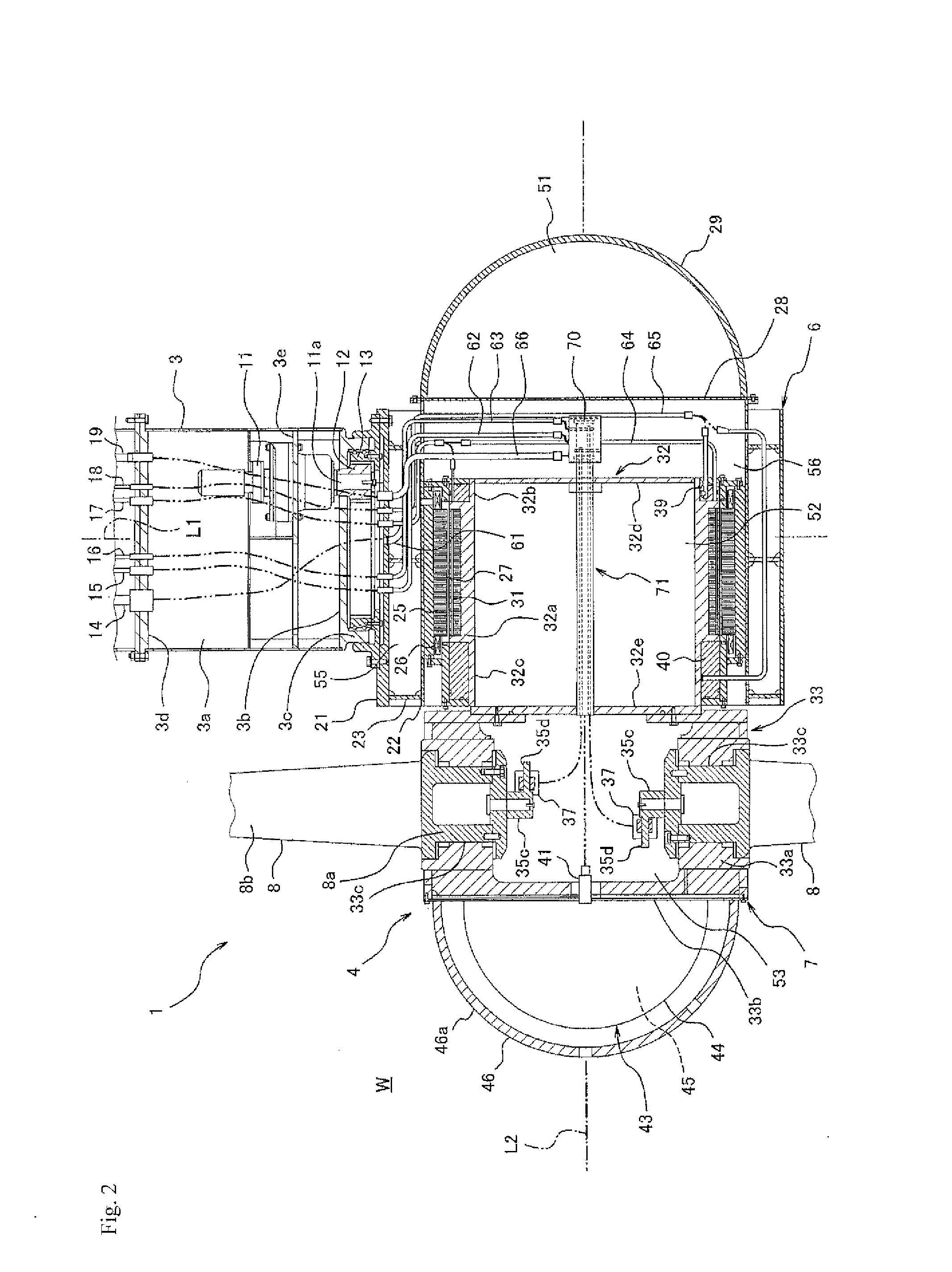
A water flow electricity generating device includes: an annular stator in which a coil is provided; a permanent magnet that causes a magnetic force to act on the coil; a rotor main body that is disposed on an inner circumferential side of a stator core to support the permanent magnet; a blade support unit that is provided on a front side of the rotor main body; a rotor that includes a rotating blade projecting radially outward from the blade support unit; and water-lubricated bearings that are provided in the stator while being opposed to the rotor main body, the water-lubricated bearings supporting loads in a thrust direction and a radial direction. The blade support unit is disposed on a front side of the rotor main body, and the rotor includes a float unit that is provided on the front side of the rotor main body.

Description

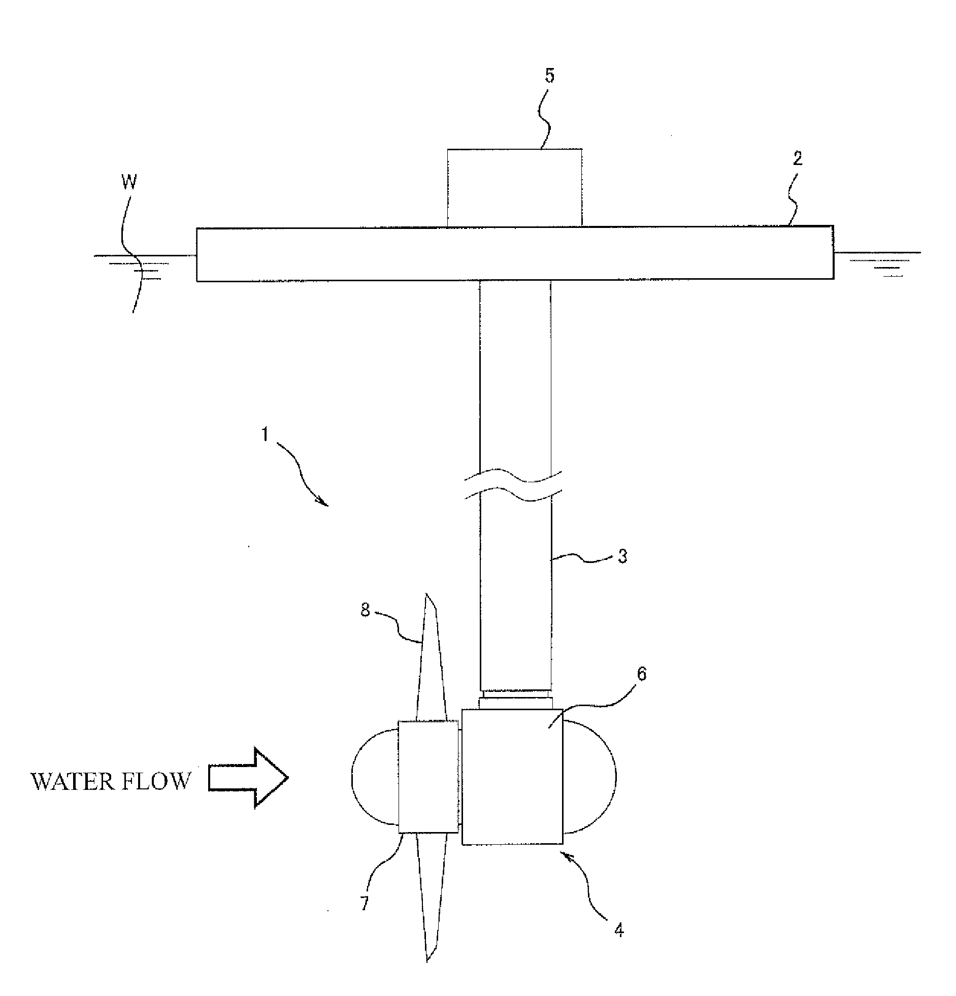
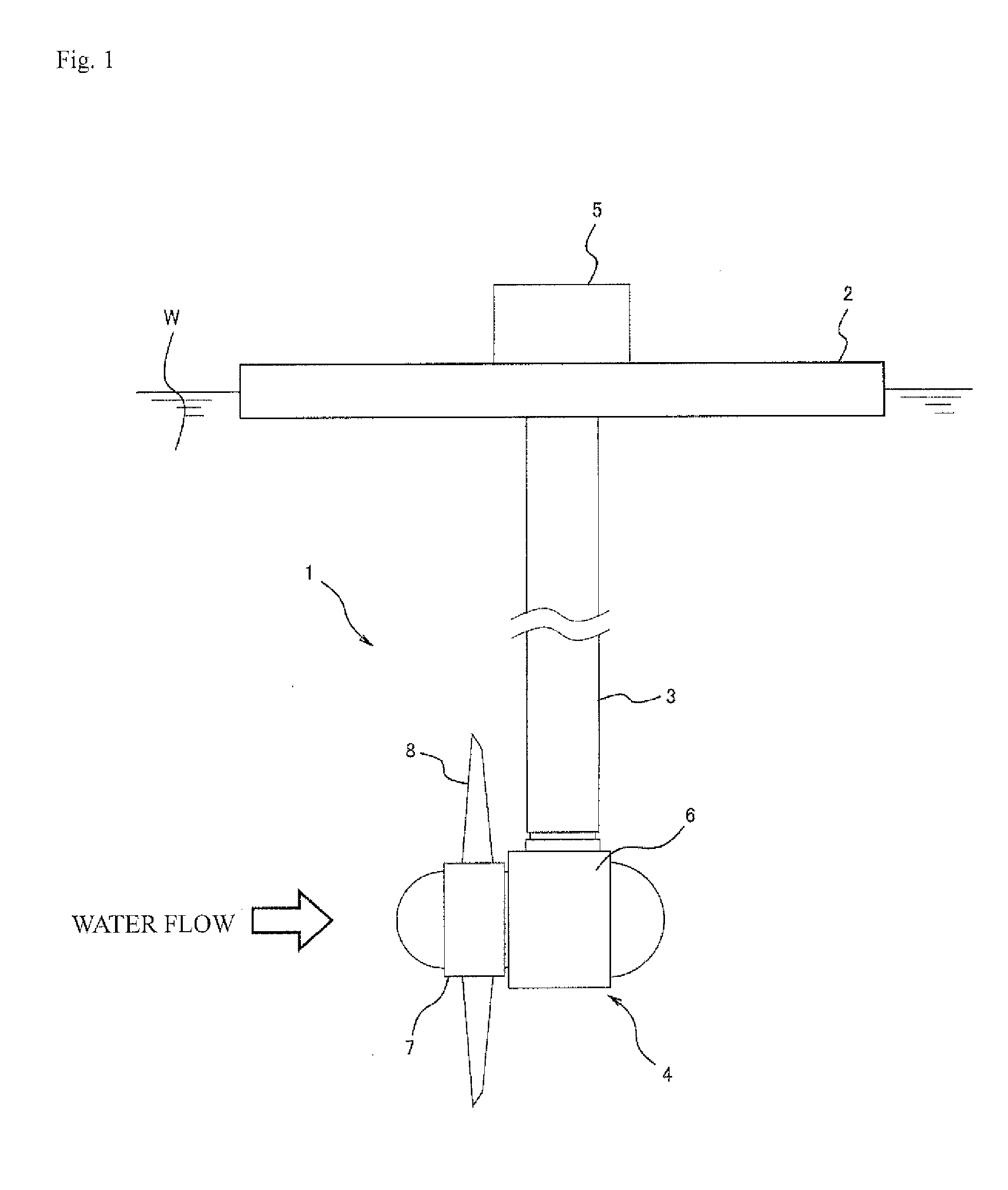
TECHNICAL FIELD[0001]The present invention relates to a water flow electricity generating device that generates electricity using water flow energy of a tidal current, an ocean current, a river current, or the like.BACKGROUND ART[0002]From the viewpoint of an energy issue or an environment issue in recent years, various investigations are made in order to utilize clean natural energy that can replace fossil energy sources such as petroleum. For example, hydro-electric power generation, in which drop energy of dammed water is used, is implemented as electricity generation of the natural energy. However, in order to perform the hydro-electric power generation, it is necessary to construct a dam that retains a water-level difference, a large amount of construction cost is required, and an environmental load also increases. On the other hand, nowadays, attention is paid to existence of a place where a large water flow (the tidal current, the ocean current, and the river current) is gene...

Claims


Application Information

Patent Timeline
IPC IPC(8): F03B13/10
CPCF03B13/10F03B3/12F03B13/264F03B17/061F05B2220/7068F05B2240/93F05B2270/1011F05B2270/1095F05B2270/18H02K5/1285H02K7/088H02K7/1823Y02E10/20Y02E10/30
Inventor KIYOSE, HIROMITSUOWAKI, KIYOTOYANASE, ETSUYAMURASE, YOUHEIOKAWA, HIROYASU
Owner KAWASAKI HEAVY IND LTD
Learn More