
Method for encoding and decoding image information and device using same

a technology of image information and decoding method, applied in the field of prediction technology, can solve the problems of increasing the cost of transmitting and storing data, and achieve the effects of reducing the degree of complexity, improving the efficiency of coding, and effectively selecting

Active Publication Date: 2013-10-17
LG ELECTRONICS INC
View PDF12 Cites 76 Cited by
  • Summary
  • Abstract
  • Description
  • Claims
  • Application Information

AI Technical Summary

Benefits of technology

The present invention improves efficiency in video coding by effectively selecting a reference picture for skipping mode of inter-prediction and effectively deriving the reference index of a temporal merge candidate. This reduces complexity and increases efficiency.

Problems solved by technology

Accordingly, if video data is transmitted using a medium such as an existing wired / wireless broadband line, or video data is stored using an existing storage medium, the costs of transmitting and storing data are also increased.

Method used


Image

  • Method for encoding and decoding image information and device using same
  • Method for encoding and decoding image information and device using same
  • Method for encoding and decoding image information and device using same

Examples


embodiment 1

Regarding the Deriving of the Reference Index of a Temporal Merge Candidate

[0191]Referring to FIG. 10, a reference index refIdxLXA (X is 0 or 1) may be derived from the block A1 1020 as follows.

[0192]If the block A1 1020 that covers the location (xP−1, yP+nPSH−1) of a sample is available and prediction mode is not intra-prediction mode MODE_INTRA, refIdxLX [xP−1, yP+nPSH−1] is assigned to the reference index refIdxLXA. The sample at the location (xP−1, yP+nPSH−1) may be a luma sample, and the block A1 1020 that covers the location (xP−1, yP+nPSH−1) of the sample and the current block 1000 may be prediction units.

[0193]If the block A1 1020 that covers the location (xP−1, yP+nPSH−1) of the sample is not available or prediction mode is intra-prediction mode MODE_INTRA, a value of −1 is assigned to the reference index refIdxLXA.

[0194]Referring to FIG. 10, a reference index refIdxLXB (X is 0 or 1) may be derived from the block B1 1040 as follows.

[0195]If the block B1 1040 that covers the...

embodiment 2

Regarding the Deriving of the Reference Index of a Temporal Merge Candidate

[0212]The present embodiment proposes a method of simply deriving the reference index of a temporal merge candidate for a current block when merge mode or merge skip mode is applied to the current block.

[0213]In the present embodiment, a fixed value may be used as the reference index of a temporal merge candidate for a current block. For example, in the present embodiment, the reference index refIdxLX of the temporal merge candidate may be designated as 0.

embodiment 3

Regarding the Deriving of the Reference Index of a Temporal Merge Candidate

[0214]In the present embodiment, unlike in the embodiment 2, from among the reference indices of temporal merge candidates, the reference index refIdxL0 of a reference picture list L0 is fixed to 0 and the reference index refIdxL1 of a reference picture list L1 is fixed to 1.

[0215]Accordingly, the reference index of a temporal merge candidate for a current block may be determined as in Equation 3 below.

refIdxL0=0

refIdxL1=refIdxL0+1=1   


PUM


Abstract

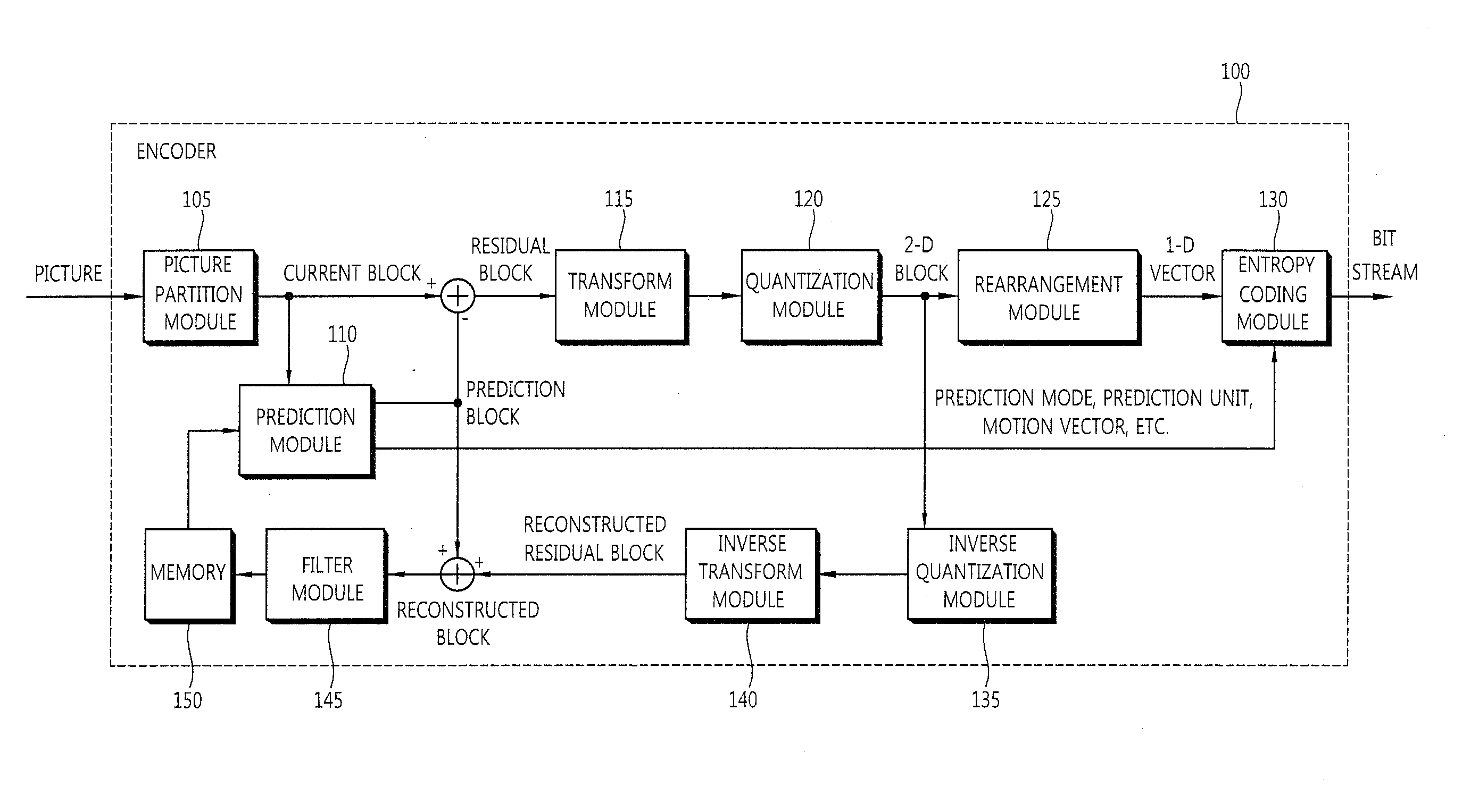
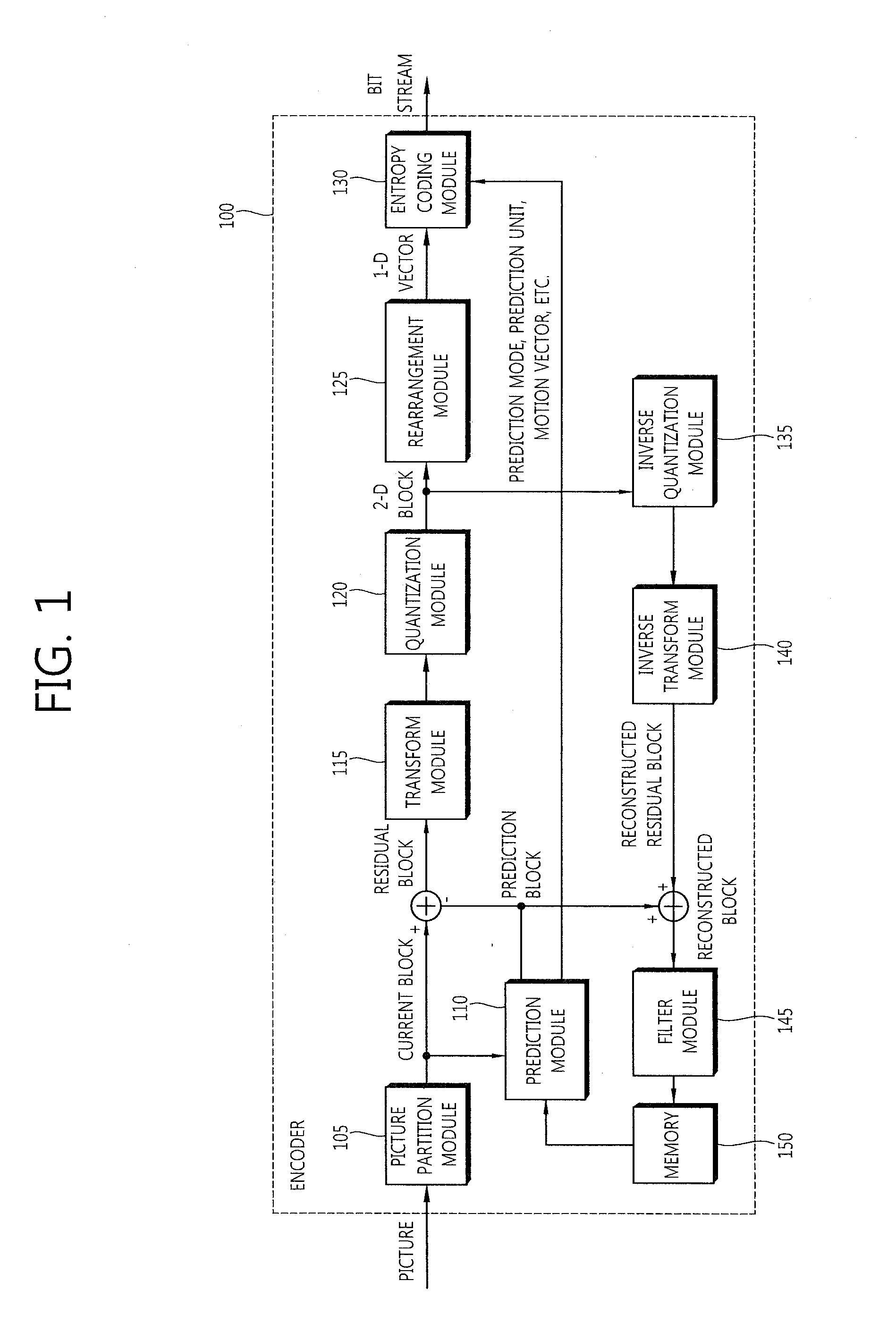
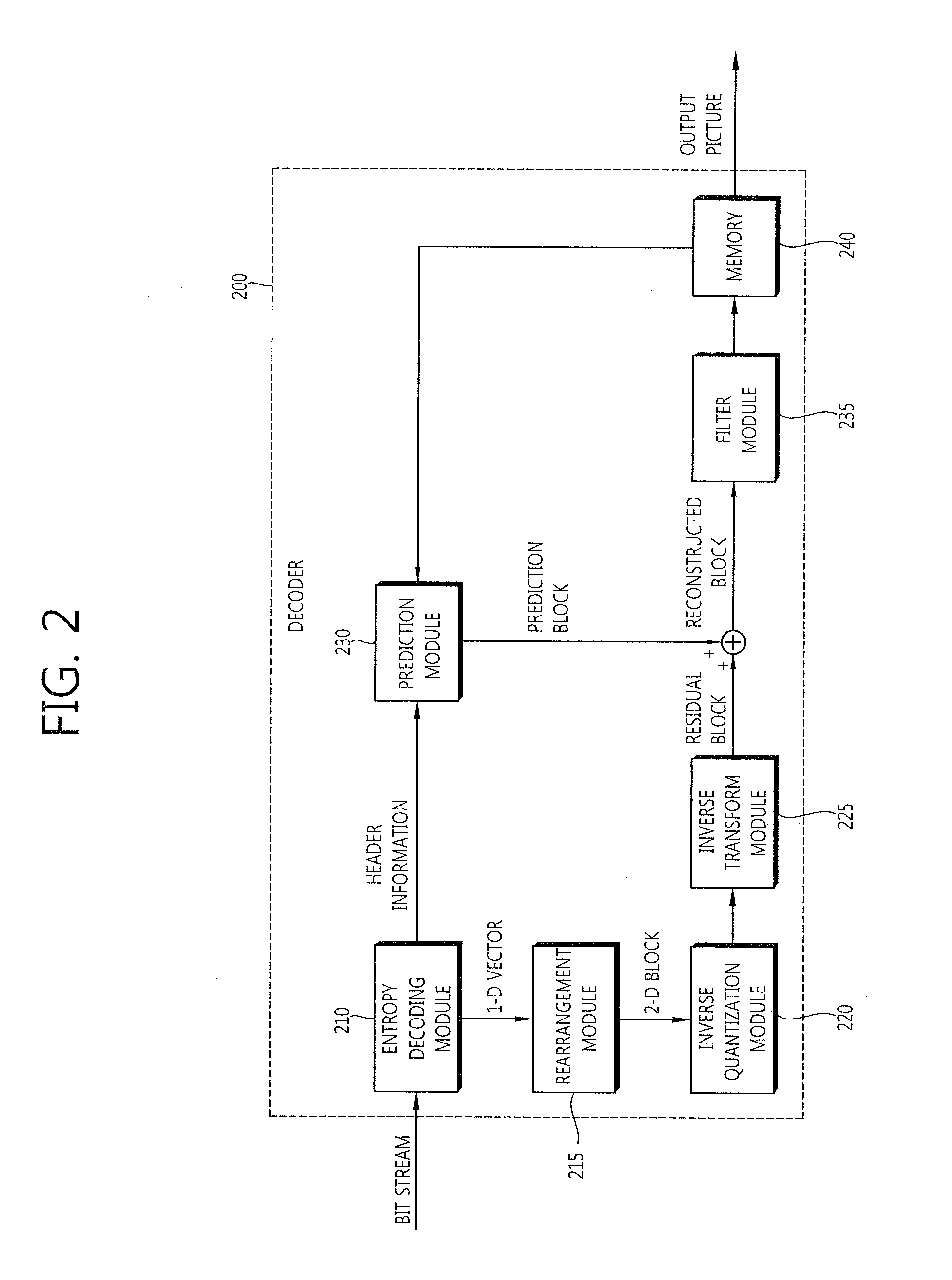
The present invention relates to the encoding and decoding of image information. According to the present invention, the decoding method comprises the steps of: entropy-decoding received information; performing inter prediction on a current block based on the entropy-decoded information; and restoring images by using the prediction results, wherein, in the inter prediction step, a skip mode or merge mode is applied to the current block and movement information of the current block may be determined based on the movement information of a neighboring block of the current block.

Description

TECHNICAL FIELD[0001]The present invention relates to video compression technology, and more particularly, to inter-prediction technology.BACKGROUND ART[0002]The need for videos having high resolution and high quality has recently been increasing in various fields. As the resolution and quality of a picture is improved, however, the amount of data in the video is also likewise increased. Accordingly, if video data is transmitted using a medium such as an existing wired / wireless broadband line, or video data is stored using an existing storage medium, the costs of transmitting and storing data are also increased. In order to effectively transmit, store, and play information within a picture having high resolution and high quality, video compression technology utilizing high efficiency can be used.[0003]In order to improve video compression efficiency, inter-prediction and intra-prediction can be used. In inter-prediction, pixel values within a current picture are predicted from a pic...

Claims


Application Information

Patent Timeline
Patent Type & Authority Applications(United States)
IPC IPC(8): H04N7/36
CPCH04N19/00575H04N19/105H04N19/139H04N19/176H04N19/503H04N19/513H04N19/517H04N19/56H04N19/593H04N19/11H04N19/573H04N19/58H04N19/109H04N19/122H04N19/70H04N19/91H04N19/132
Inventor PARK, SEUNGWOOKLIM, JAEHYUNJEON, YONGJOONHENDRY, HENDRYCHOI, YOUNGHEESUNG, JAEWONKIM, JUNGSUNJEON, BYEONGMOONPARK, JOONYOUNG
Owner LG ELECTRONICS INC
Learn More