
Portable device and method for field testing proppant

a portable device and field testing technology, applied in the direction of material strength using tensile/compressive forces, fluid removal, survey, etc., can solve the problem of introducing a risk of proppant flowing out of fractures along with the produced fluid

Active Publication Date: 2013-09-12
SAUDI ARABIAN OIL CO
View PDF6 Cites 43 Cited by
  • Summary
  • Abstract
  • Description
  • Claims
  • Application Information

AI Technical Summary

Benefits of technology

The patent describes methods and devices for analyzing proppant used in wellbores. The testing device includes a frame for transporting to the wellsite, a vessel for holding the proppant, a gas to liquid pressure intensifier, and a ram member for compressing the proppant to simulate a downhole condition. The device can also include sensors to monitor properties of the proppant and electronics for analyzing the data. The technical effects of the patent include providing a way to analyze proppant in real-time, allowing for better decision-making during wellbore construction.

Problems solved by technology

Producing from a well whose fractures have uncured resin coated proppant introduces a risk of proppant flowing out of the fractures along with the produced fluid.

Method used


Image

  • Portable device and method for field testing proppant
  • Portable device and method for field testing proppant
  • Portable device and method for field testing proppant

Examples


Embodiment Construction

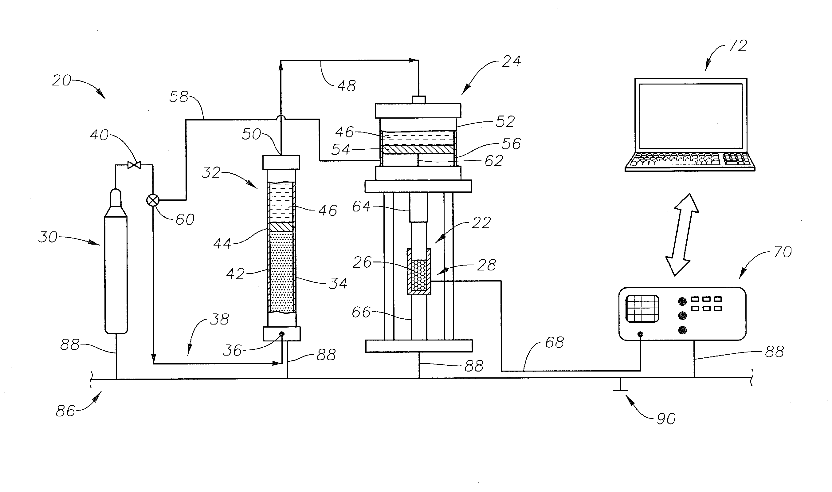
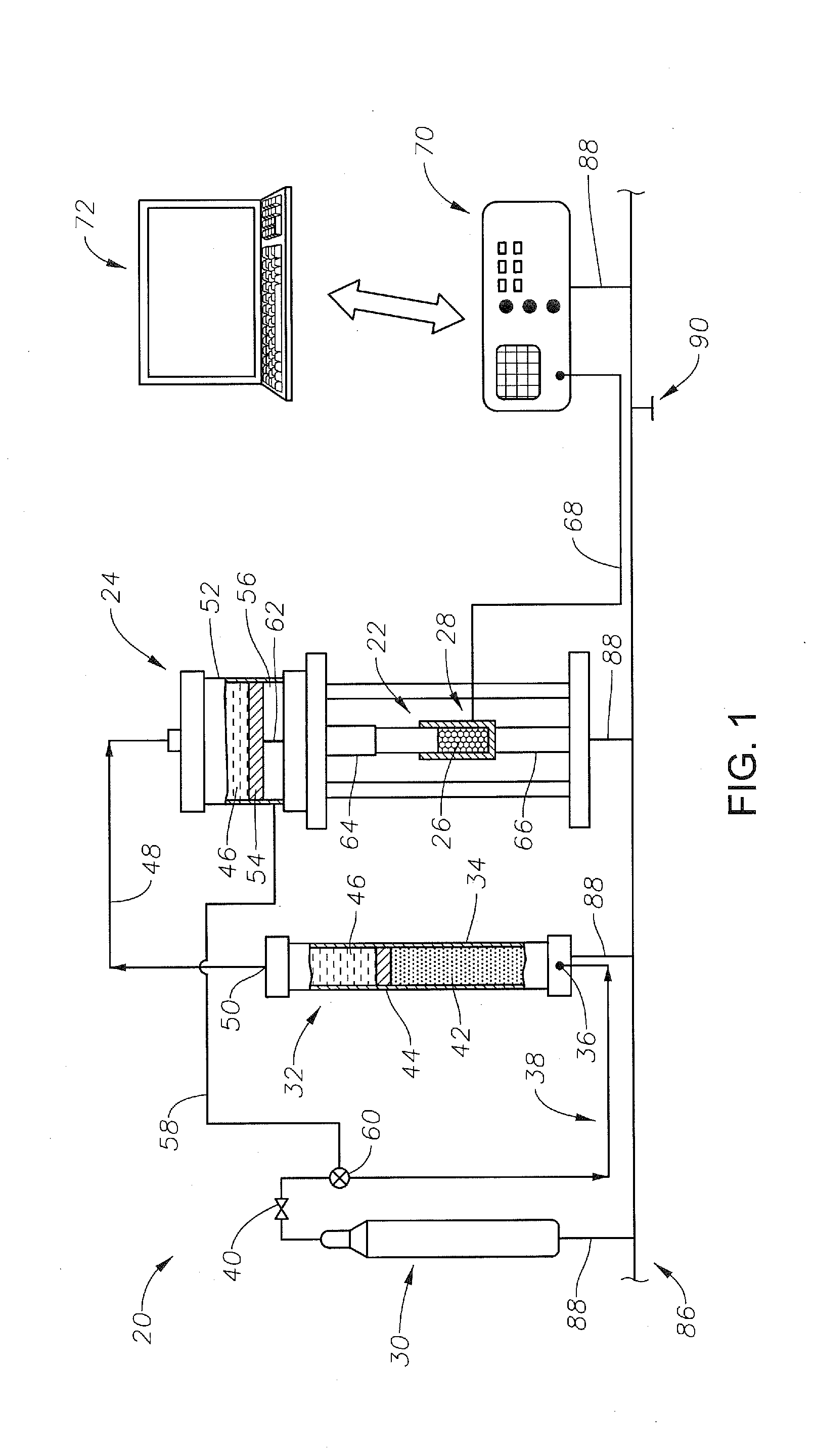
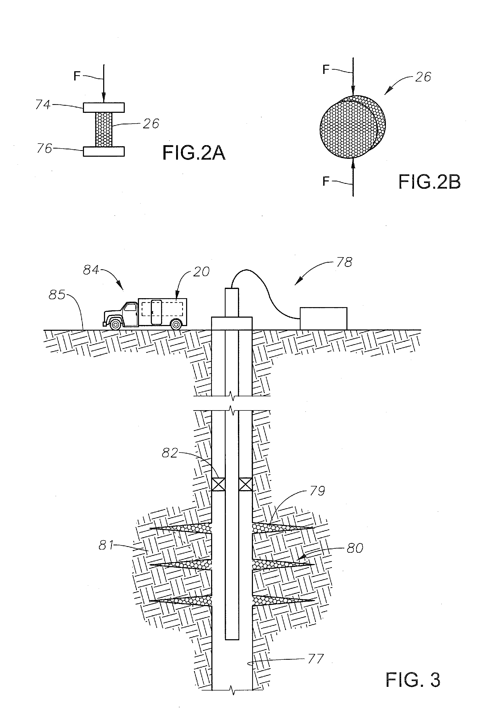
[0016]A testing system 20 for the field testing of resin-coated proppant is schematically illustrated in FIG. 1. The testing system 20 includes a test cell 22 shown mounted within a press assembly 24. The test cell 22 as shown includes a proppant sample 26 disposed in an oedometer 28. As will be described in more detail below, charging the press assembly 24 in turn compresses the proppant sample 26 within the oedometer 28. In an example, the oedometer 28 acts as a vessel for receiving the proppant sample 26. A pressurized fluid supply 30 is schematically illustrated and is used for pressurizing an intensifier 32. The intensifier 32 of FIG. 1 includes an upstream cylinder 34, having a fluid inlet 36 connected to the fluid supply 30 via line 38. A valve 40 is in line 38 for selectively isolating the fluid supply 30 from intensifier 32. Pressurized gas 42 is shown schematically within the upstream cylinder 34 having flowed through line 38 and inlet 36 into the upstream cylinder 34. Als...


PUM

PropertyMeasurementUnit
pressureaaaaaaaaaa
weightaaaaaaaaaa
cure timeaaaaaaaaaa

Abstract

A testing system and method for evaluating the time required for shutting in a well after packing fractures in the well with a proppant having curable resin. At the well site, a sample of the proppant is compressed and heated in a portable unit. While the sample is being heated and compressed, its properties are being monitored to determine if the resin in the proppant has cured. Recording the time required for the proppant to cure provides an indication of how long to shut in the well after packing the fractures with the proppant. The portable unit includes a gas to fluid intensifier for compressively stressing the sample and a heat source for heating the sample. Sensors adjacent the proppant sample monitor the properties.

Description

CROSS REFERENCE TO RELATED APPLICATIONS[0001]This application claims priority to and the benefit of co-pending U.S. Provisional Application Ser. No. 61 / 607,633, filed Mar. 7, 2012, the full disclosure of which is hereby incorporated by reference herein for all purposes.BACKGROUND OF THE INVENTION[0002]1. Field of the Invention[0003]The present invention relates to a system and method for completing a wellbore. More specifically, the invention relates to a device that is portable to a wellbore and used for field testing of proppant.[0004]2. Description of the Related Art[0005]Hydrocarbon producing wellbores extend subsurface and intersect subterranean formations where hydrocarbons are trapped. The wellbores generally are created by drilling system having a drill bit mounted on an end of a drill string made up of tubulars threaded together. Usually a drive system is used to rotate the drill string and bit, and is set above an opening to the wellbore. As the bit is rotated, cutting ele...

Claims


Application Information

Patent Timeline
Patent Type & Authority Applications(United States)
IPC IPC(8): G01N3/00E21B43/267
CPCG01N3/00E21B43/267C09K8/805G01N15/0806G01N33/442G01N3/08
Inventor ALQAM, MOHAMMAD H.ABASS, HAZIM HUSAINAL-SHAMMARY, HUSSAIN A.CALIBOSO, EDWIN T.
Owner SAUDI ARABIAN OIL CO
Learn More