
Ballistic Wall

a ballistic wall and wall technology, applied in the field of walls, can solve the problems of significant ongoing expense, concrete walls require a substantial footing or foundation, and the range takes significant time and expense to construct, so as to improve the appreciation of the contribution of the art

Inactive Publication Date: 2013-09-12
BERGIADIS WILLIAM LEE
View PDF7 Cites 8 Cited by
  • Summary
  • Abstract
  • Description
  • Claims
  • Application Information

AI Technical Summary

Benefits of technology

The present invention provides an improved ballistic wall that has all the advantages of the prior art. The wall is made up of interlocking blocks made of bullet-resistant material and acoustic sound absorbing material. The blocks have a protruding tongue and a groove to allow them to be interlocked. The blocks can be formed of a stack of panels, with an interior panel offset from the surface panels. The blocks can be arranged in a running bond, and there are additional features of the invention that will be described hereinafter. Overall, the invention provides a stronger and more effective ballistic wall.

Problems solved by technology

Another consequence is the range takes significant time and expense to construct.
Furthermore, considerable ongoing expense occurs because the berms must be erosion controlled, periodically the lead projectiles must be removed, and the berms must be re-compacted.
However, concrete walls require a substantial footing or foundation because they are heavy.
This design increases cost substantially and requires a 28 day cure time.
In addition, in order to provide ballistic protection, a minimum of 5,000 PSI concrete is required, which further adds to the wall's cost.
This design is time-consuming to construct and much more expensive than dirt berms.
This reflected sound level, when added to the actual gunfire sound level, produces very high, unhealthy sound levels that will carry for a length of over ¾ of a mile.
This sound level can be very intrusive to neighbors or adjacent buildings within this ¾ mile radius.

Method used


Image

  • Ballistic Wall
  • Ballistic Wall
  • Ballistic Wall

Examples


Embodiment Construction

[0021]A preferred embodiment of the ballistic wall of the present invention is shown and generally designated by the reference numeral 10.

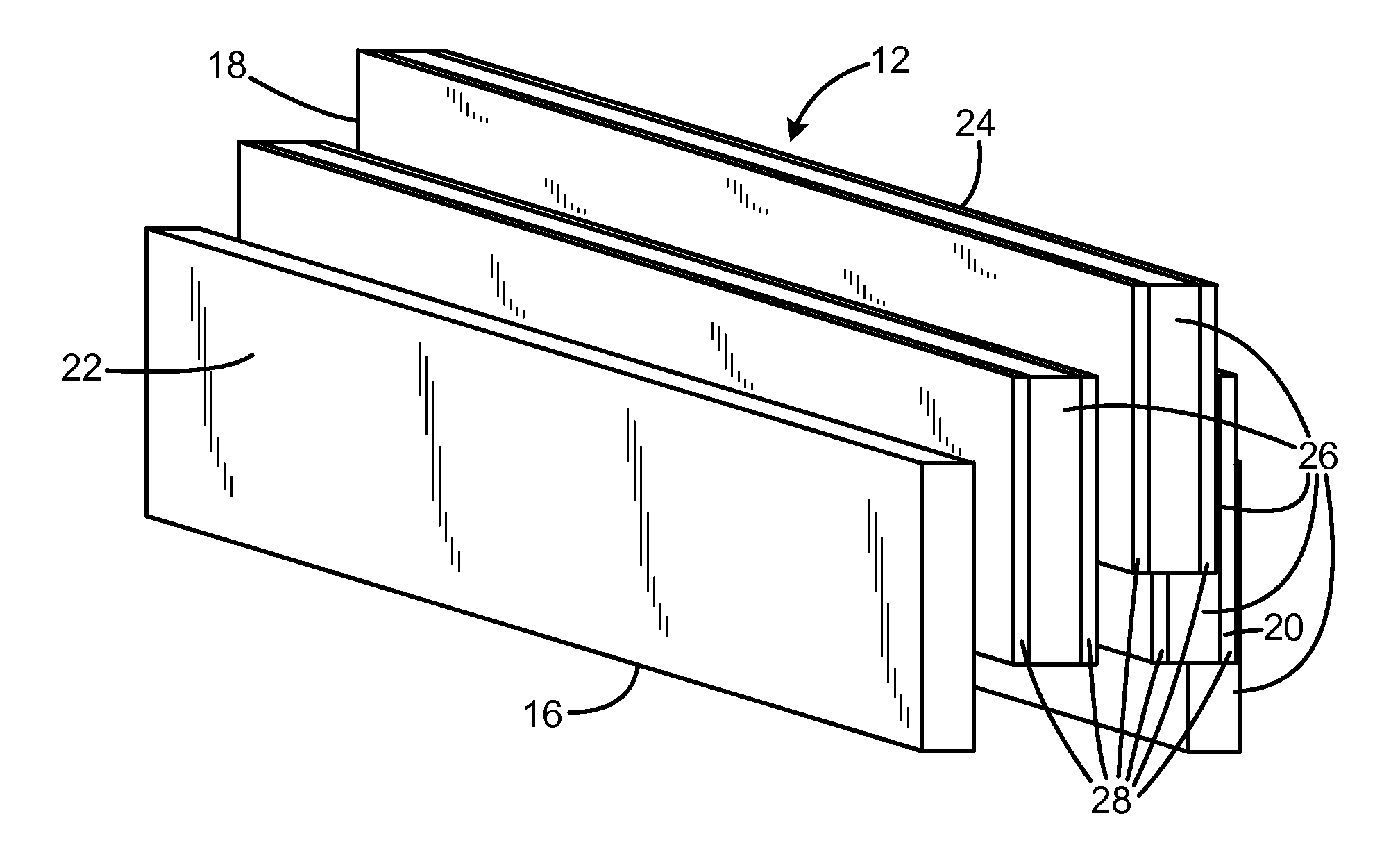
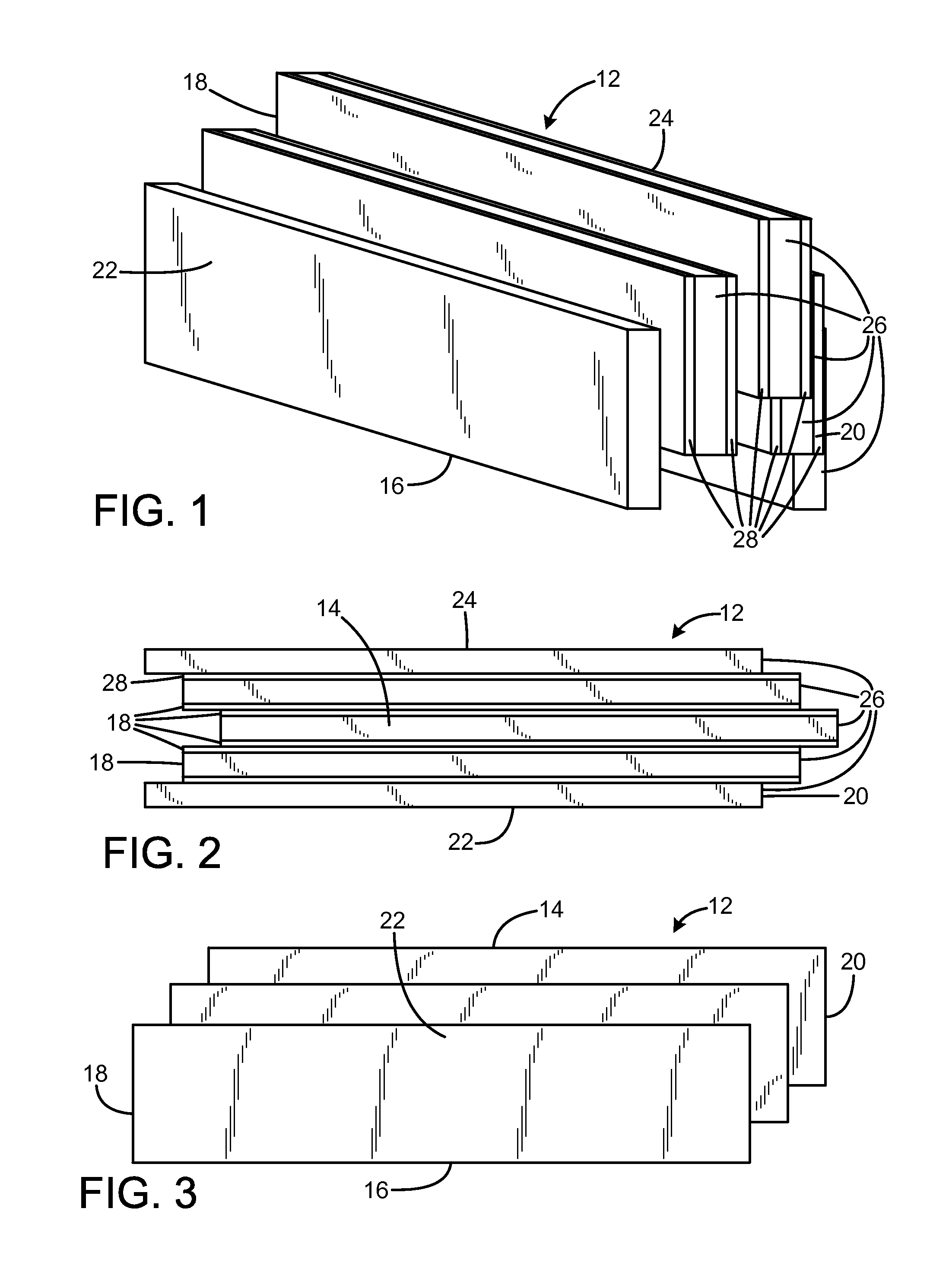
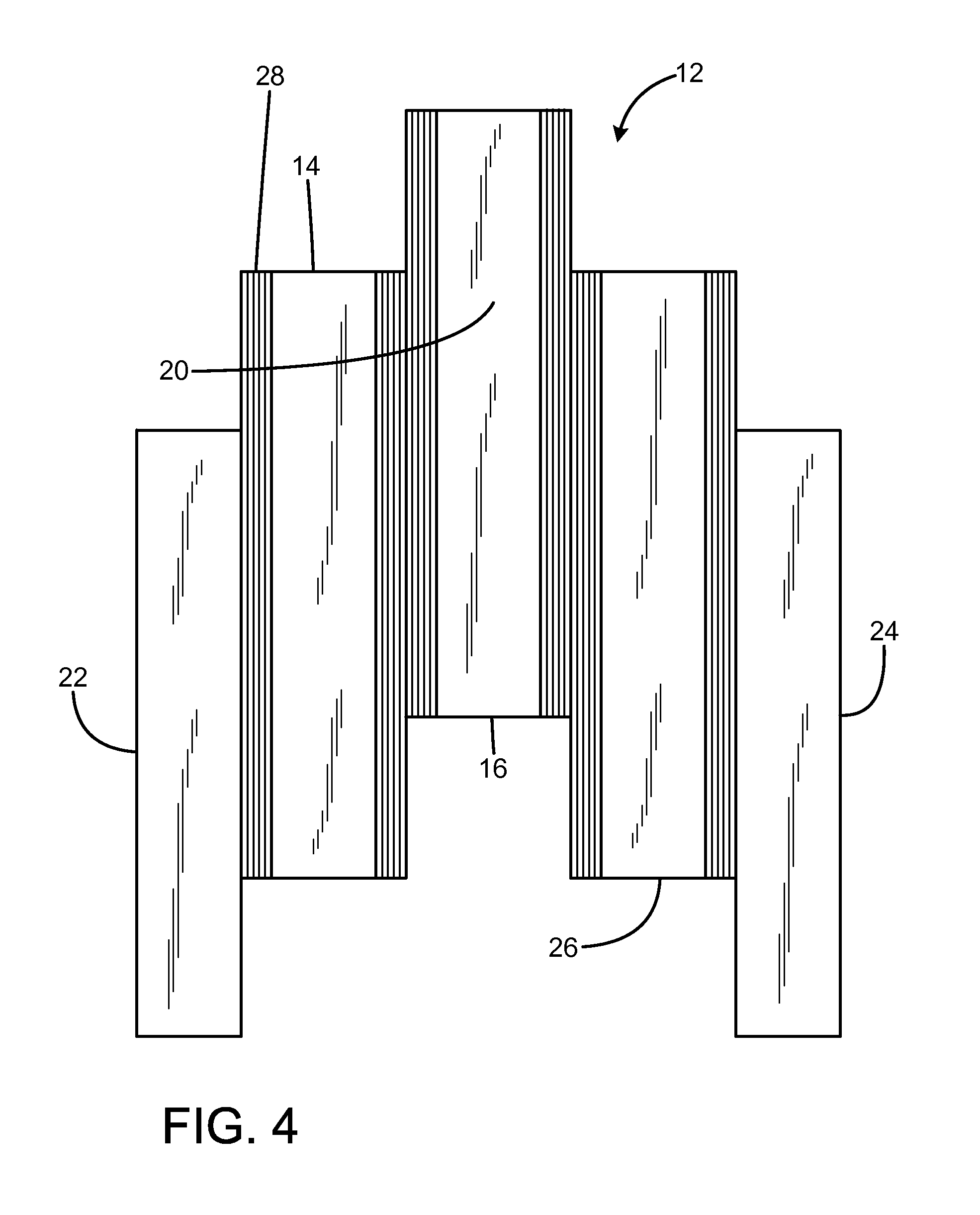
[0022]FIGS. 1-4 illustrate the improved panel 12 of the present invention. More particularly, the panel has a frame 64 having a top 14, a bottom 16, a left side 18, a right side 20, a front 22, and a rear 24. The panel is a sandwich consisting of five acoustical board layers 26. The acoustical board layers are joined by ballistic material layers 28. The acoustical board layers and ballistic material layers are offset longitudinally and laterally (essentially diagonally) from adjacent layers to form dovetails at the top, bottom, left end, and right end.

[0023]In the current embodiment, the ballistic material layers are made of a polymer composite resin mixed with multiple layers of a fiberglass mesh fabric material. The polymer composite resin binding agent bonds the multiple layers of fiberglass mesh to stop the penetration of projectiles. The two ...


PUM


Abstract

Ballistic walls include a plurality of interlocking blocks formed of a bullet-resistant material, a first portion of the periphery of each block having a protruding tongue, a second portion of the periphery of each block defining a groove sized to receive the tongue, and the tongues and grooves of adjacent blocks being mated to each other to form an interlocked structure. Each block may be formed of a stack of panels having a first surface panel, a second surface panel, and an interior panel, wherein the interior panel is offset from the first and second surface panels to form the tongues and to define the grooves. Each block may be formed of a stack of five panels offset from each other. The blocks may be arranged in a running bond, such that the vertical seams of one course are offset from the vertical seams of an adjacent course.

Description

FIELD OF THE INVENTION[0001]The present invention relates to walls for stopping and capturing projectiles, and to projectile slowing and capturing elements with sound absorbing properties.BACKGROUND OF THE INVENTION[0002]Traditionally, outdoor shooting ranges utilize dirt berms to provide side ballistic protection. Although dirt berms are used effectively in this application, they have a number of disadvantages. First, dirt berms must have a 2:1 compacted slope. This means that for every foot of height, the berm must be 2 feet wide. A 16 foot high dirt berm must be 32 feet wide, which occupies a considerable area. Given that two berms are required for sidewall protection, this means that 64 feet must be devoted to the berms alone. Another consequence is the range takes significant time and expense to construct. Furthermore, considerable ongoing expense occurs because the berms must be erosion controlled, periodically the lead projectiles must be removed, and the berms must be re-com...

Claims


Application Information

Patent Timeline
Patent Type & Authority Applications(United States)
IPC IPC(8): F41H5/24F41H5/02F41H5/04
CPCF41H5/013F41J11/02F41H5/24F41H5/0471
Inventor BERGIADIS, WILLIAM LEE
Owner BERGIADIS WILLIAM LEE
Learn More