
Self-contained bathroom

a self-contained, bathroom technology, applied in the direction of wheeled lavatories, domestic plumbing, domestic applications, etc., can solve the problems of weakening the aforementioned floor, requiring major work, and complex installation of evacuation ducts in rooms

Inactive Publication Date: 2013-09-12
CORNILLE ALAIN
View PDF11 Cites 11 Cited by
  • Summary
  • Abstract
  • Description
  • Claims
  • Application Information

AI Technical Summary

Benefits of technology

The patent describes how a bathroom can collect and store its own waste without requiring any extra effort from the user. This means that there's no longer a need for installing a separate drainage system or adding an oversized tank underneath the floor.

Problems solved by technology

The technical problem addressed in this patent is the difficulty and expense of installing traditional wastewater evacuation ducts in bathrooms, which may also affect the integrity of floors and cause other issues like limited accessibility. To solve these challenges, there is a need for an autonomous bathroom design that eliminates the requirement for separate drainages and allows for easy placement without compromising the floor's strength or requiring significant modifications.

Method used


Image

  • Self-contained bathroom
  • Self-contained bathroom
  • Self-contained bathroom

Examples


Embodiment Construction

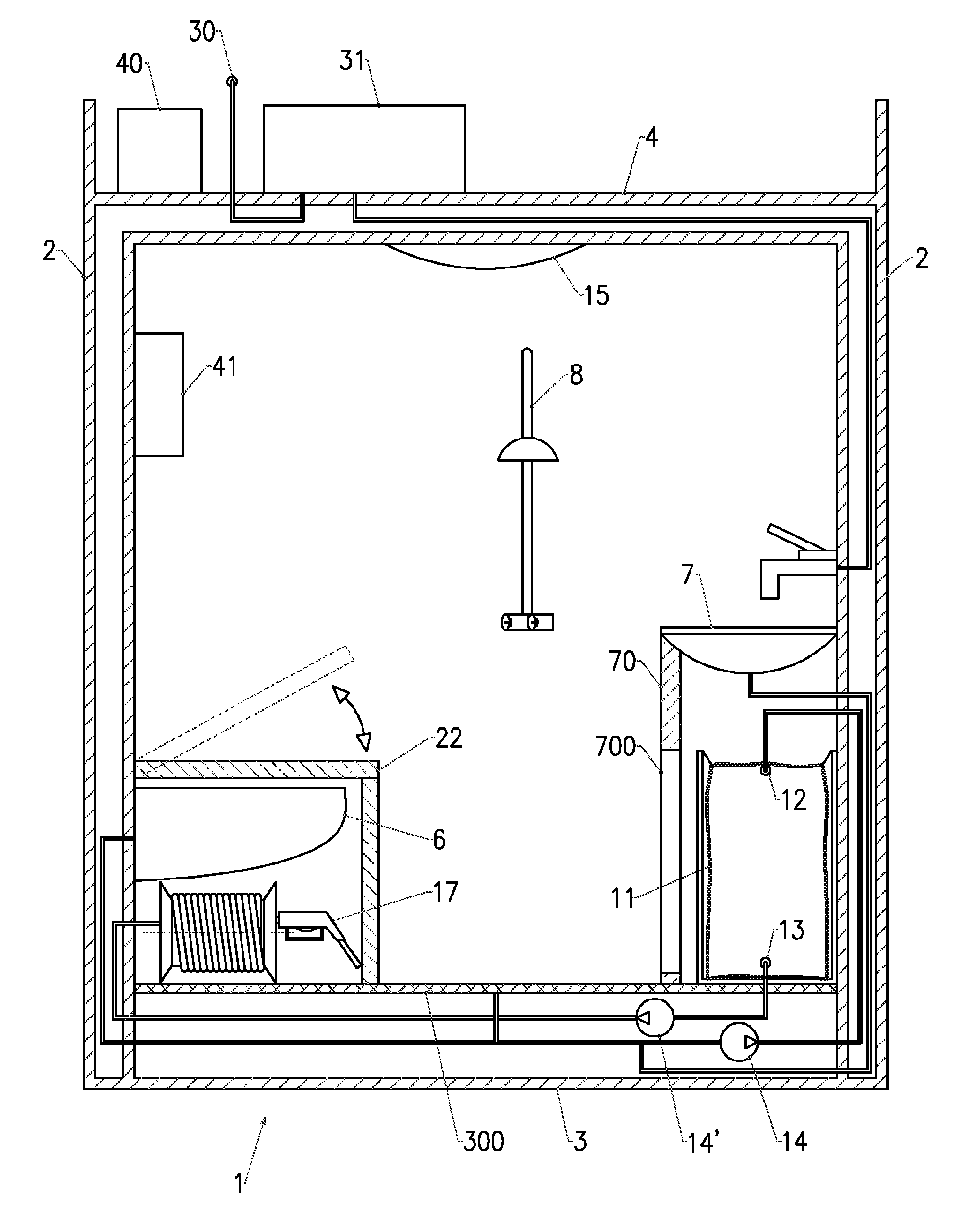
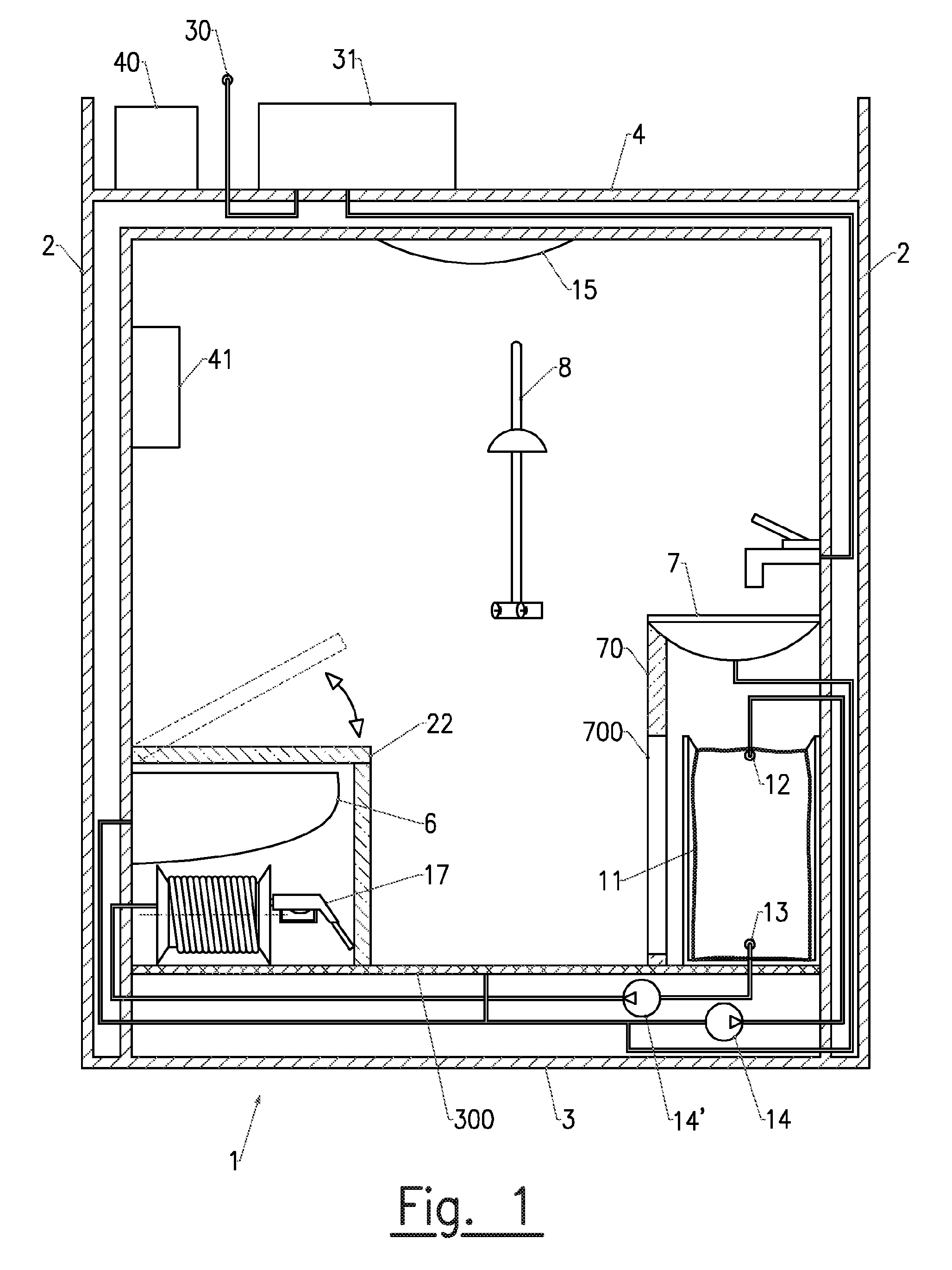
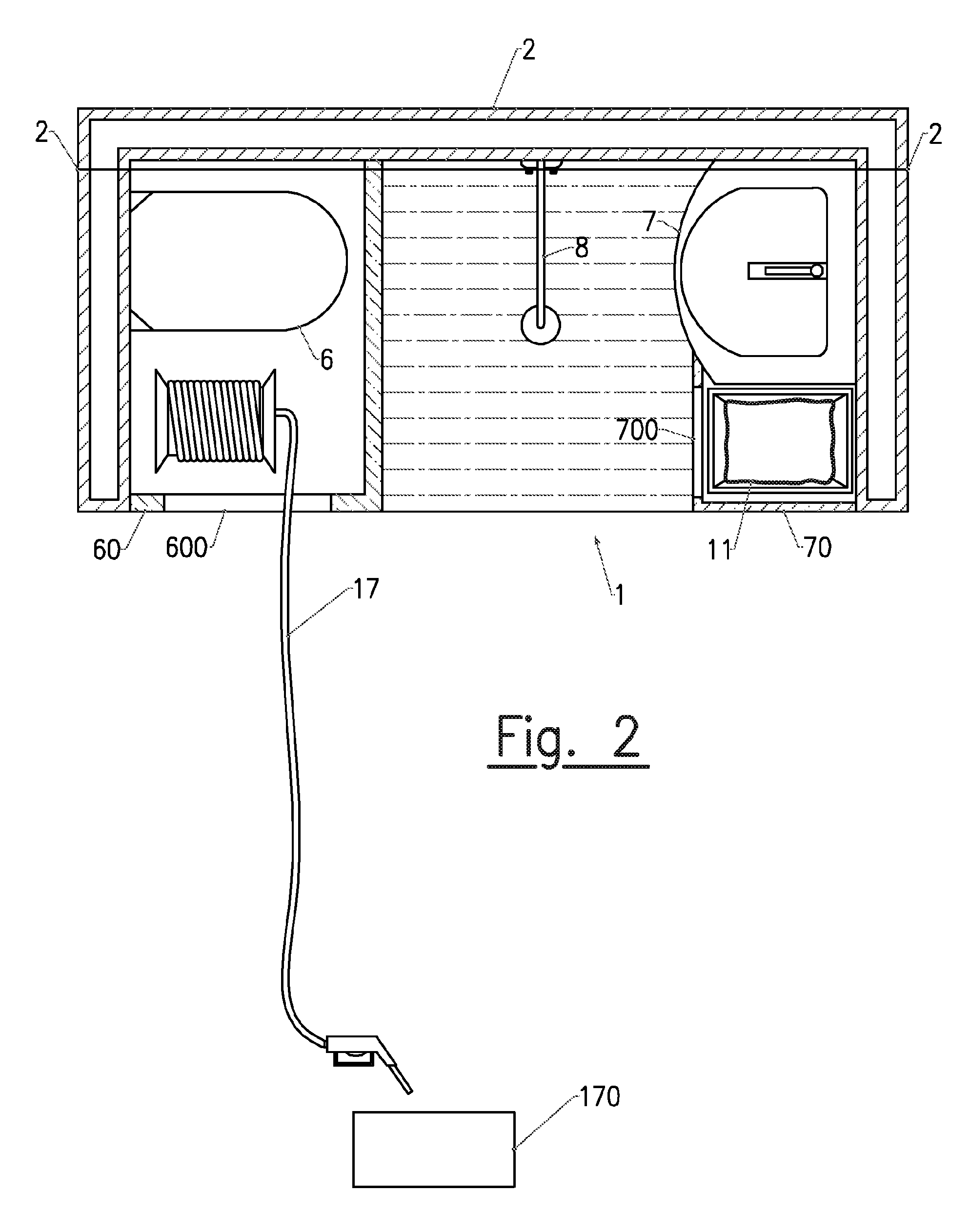
[0034]Referring to FIGS. 1 and 2, the bathroom (1) object of the invention is designed to be installed in a room of a dwelling, this room not being originally designed for this purpose. This can be for example a bedroom of a person having reduced mobility, wherein, for practical reasons, one wishes to directly install a bathroom.

[0035]This bathroom is particularly well suited in the case of home hospitalization of persons having reduced mobility. It allows these people:

[0036]to avoid or delay their placement in a specialized institution,

[0037]to be provided them with conveniences (toilet, shower, washbasin) nearby and easily accessible,

[0038]to facilitate the work of their aides, their housekeepers and their families.

[0039]to save them from disrupting the life of others living in the dwelling, while preserving an intimacy and closeness with their circle.

[0040]The bathroom (1) includes a prefabricated enclosure designed to be placed on the floor (100) of the room. This enclosure can ...


PUM


Abstract

The invention relates to a self-contained bathroom comprising a prefabricated chamber intended to be placed on the floor of a room in a dwelling, said chamber containing sanitary fittings (6, 7, 8). The bathroom also includes: a means (30) for supplying clean water to the prefabricated chamber; a means (14) for collecting the wastewater generated by the sanitary fittings (6, 7, 8); and a tank (11) for storing the wastewater, said tank being connected to a drain means (14′) placed inside the prefabricated chamber in order to drain the wastewater stored in the tank. The invention is characterised in that the drain means (14′) is connected to a extendable hose (17) positioned inside the prefabricated chamber, and, while the tank remains inside the chamber, the extendable hose can be used to convey and direct the drain flow towards a drain point outside the chamber.

Description


Claims


Application Information

Patent Timeline
Owner CORNILLE ALAIN
Learn More