
Method of performing automatic commissioning of a network

a technology of automatic commissioning and network, applied in the field of automatic commissioning of networks, can solve the problems of affecting the overall cost of the system, and involving a lot of manual inpu

Active Publication Date: 2013-08-22
SIGNIFY HLDG BV
View PDF11 Cites 101 Cited by
  • Summary
  • Abstract
  • Description
  • Claims
  • Application Information

AI Technical Summary

Benefits of technology

The patent describes a method for automatically analyzing network devices and identifying their physical location. This information can be used to control specific devices in the network according to the user's requirements. The method allows for the identification of each device in the network without any labor-intensive and expensive manual input. The network descriptive information can include information about the devices' installation plan and physical location. The method also allows for the exchange of data packets between devices and the identification of the receiving device based on the elapsed time between the broadcast and reception of the data packet. Overall, the method simplifies the process of commissioning and managing devices in a network.

Problems solved by technology

Unfortunately, the known methods of performing commissioning involve much manual input, and are time-consuming, labour-intensive and error-prone.
In fact, the commissioning of a prior art lighting control system such as a DALI system can constitute up to one third of the total cost of the system.

Method used


Image

  • Method of performing automatic commissioning of a network
  • Method of performing automatic commissioning of a network
  • Method of performing automatic commissioning of a network

Examples


Embodiment Construction

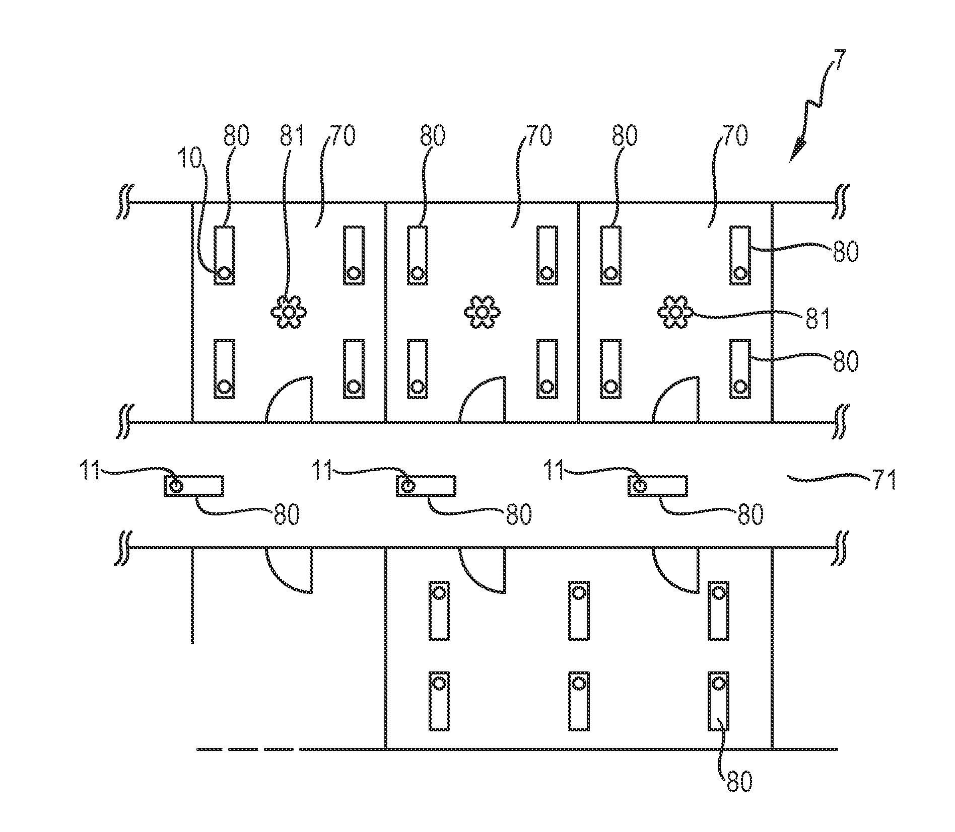
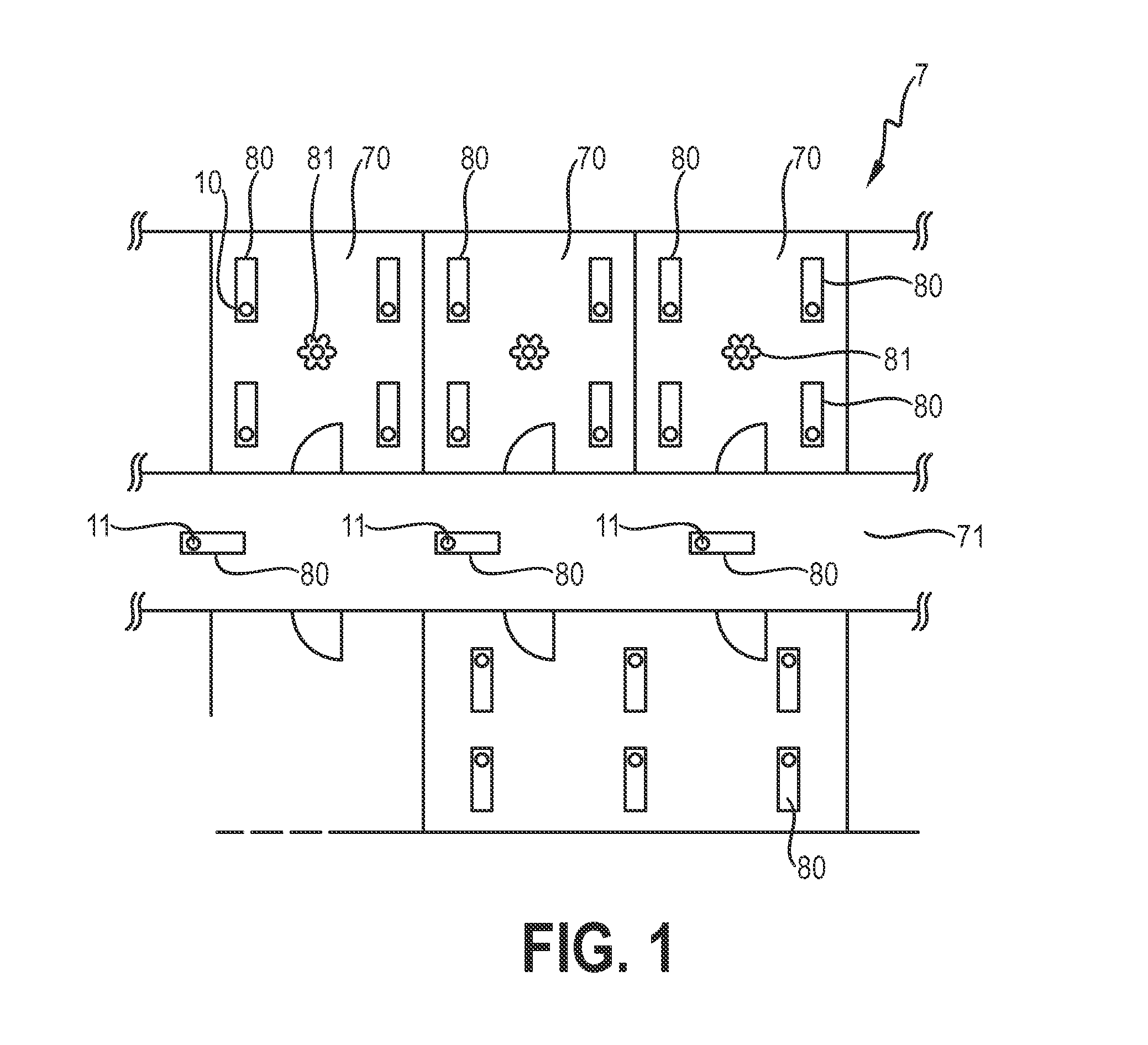
[0035]FIG. 1 shows a schematic representation of a floor plan 7 of a building with rooms 70 arranged along a corridor 71. Each room 70 contains a number of lights 80 and a light sensor 81, for example for sensing light levels with the room 70. Further lights are arranged in the corridor 71. The luminaires 80 and light sensors 81 are controllable by a lighting control system for the building. To this end, each luminaire 80 and sensor 81 incorporates a router, which can be a simple two-port bridge 10 or a multi-port bridge 11 or switch 11, as appropriate. For example, a luminaire 80 in a room 70 can incorporate a simple two-port bridge 10, while a luminaire in the corridor 71 can incorporate a switch 11 for passing commands in more than two directions. Each bridge 10, 11 can be realised to control the power supply to its luminaire 80 or sensor 81, so that the luminaires 80 and sensors 81 of the building can be individually and / or collectively controlled by the lighting control system....


PUM


Abstract

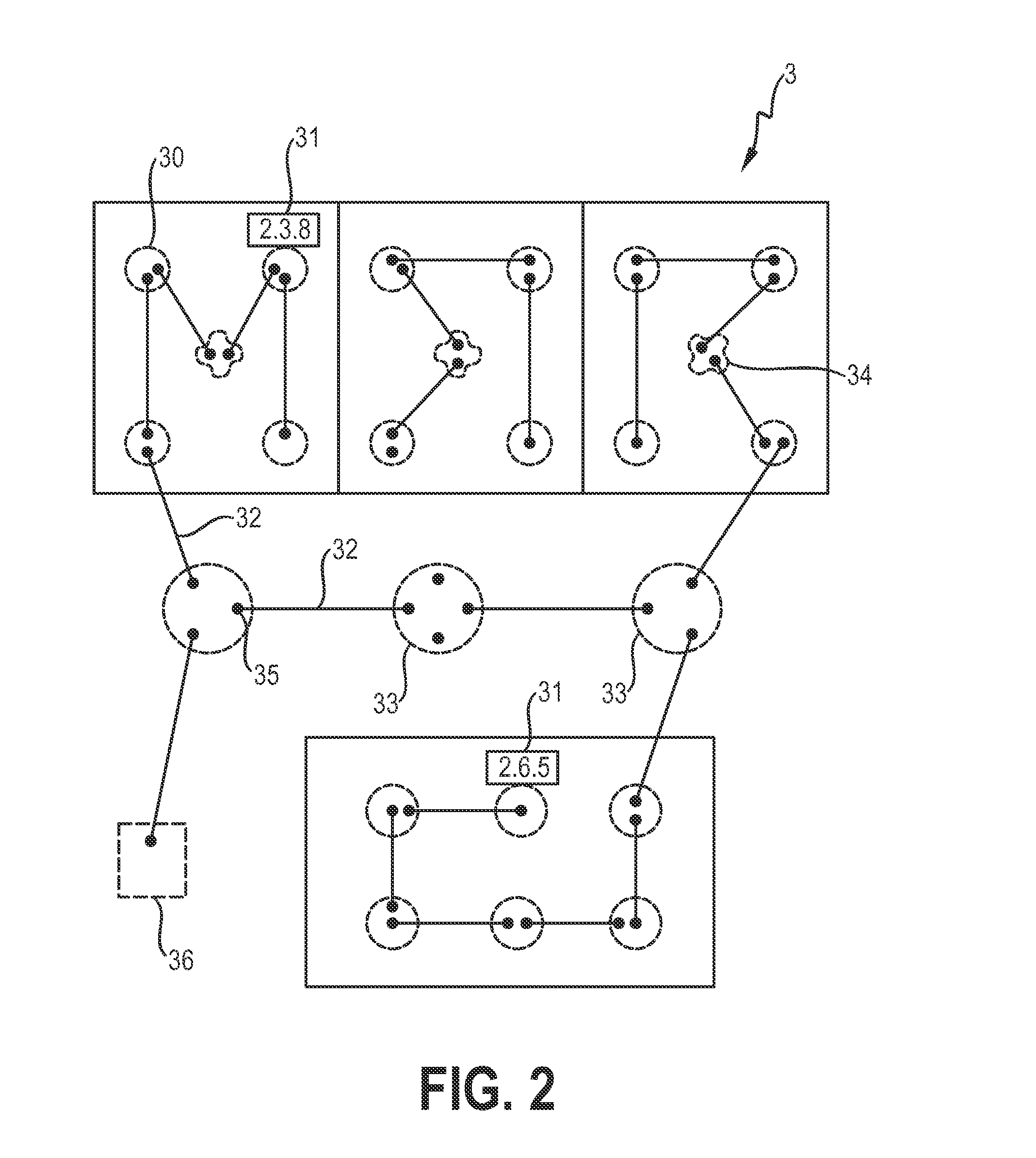
The invention describes a method of performing automatic commissioning of a network (N) comprising a plurality of network devices (10, 11, 12, 13), wherein each device (10, 11, 12, 13) is characterised by a device identifier (14) and wherein the devices (10, 11, 12, 13) are realised to exchange data packets (2), which method comprises the steps of obtaining a computer-readable installation plan (3) for the network (N), which installation plan (3) comprises a physical location descriptor (31) for devices (10, 11, 12, 13) of the network (N); deducing the network topology (T) of the network (N) from network descriptive information (40, 41, 42, 43) provided by the devices (10, 11, 12, 13) on the basis of data packets (2) exchanged between the devices (10, 11, 12, 13); and comparing the deduced network topology (T) to the installation plan (3) to allocate a physical location descriptor (31) to a device identifier (11). The invention further describes a commissioning system (1) for automatically commissioning a network (N) comprising a plurality of network devices (10, 11, 12, 13), wherein each device (10, 11, 12, 13) is characterised by a device identifier (14) and wherein each device (10, 11, 12, 13) is realised to transmit and receive data packets (2), which commissioning system (5) comprises a source (50) of a computer-readable installation plan (3) for the network (N), which installation plan (3) comprises a physical location descriptor (31) for each device (10, 11, 12, 13) of the network (N); a device control interface (55) realised to collect network descriptive information (40, 41, 42, 43) provided by the devices (10, 11, 12, 13); a topology discovery unit (53) realised to derive the network topology (T) of the network (N) from the provided network descriptive information (40, 41, 42, 43); and a commissioning unit (54) realised to compare the derived network topology (T) to the installation plan (3) to allocate a physical location descriptor (31) to a device identifier (14).

Description

FIELD OF THE INVENTION[0001]The invention describes a method of performing automatic commissioning of a network, and a commissioning system for automatic commissioning of a network.BACKGROUND OF THE INVENTION[0002]Many commercial, public or industrial buildings with many levels and many rooms avail of a control system for controlling the lighting, ventilation, air-conditioning etc. Devices such as lights or luminaires, light switches, light sensors, thermostats etc. with networking capability can be installed as part of a device network that can be centrally and automatically controlled. In a typical building such as a large office complex or a hospital, the device network may comprise many hundreds or even thousands of devices or nodes. Devices may be wireless and can communicate using a suitable wireless protocol. In a wired network such as an Ethernet network, neighbouring devices are physically wired together using a suitable connector such as a twisted pair or a co-axial cable....

Claims


Application Information

Patent Timeline
Patent Type & Authority Applications(United States)
IPC IPC(8): G06F15/177
CPCH04L12/2809G06F15/177H04L2012/285H04L41/12H05B47/18H05B47/199
Inventor WANG, XIANGYULELKENS, ARMAND MICHEL MARIEDRAAIJER, MAURICE HERMAN JOHAN
Owner SIGNIFY HLDG BV
Learn More