Numerical controller with machining curve creating function
a technology of numerical controllers and curves, applied in the field of numerical controllers, can solve the problems of large matrix calculation scale, large memory region and long computation time, and inability to achieve smooth approximated point sequences
- Summary
- Abstract
- Description
- Claims
- Application Information
AI Technical Summary
Benefits of technology
Problems solved by technology
Method used
Image

Examples
first embodiment
[0059]Hereinafter, a numerical controller with a machining curve creating function according to the present invention will be described.
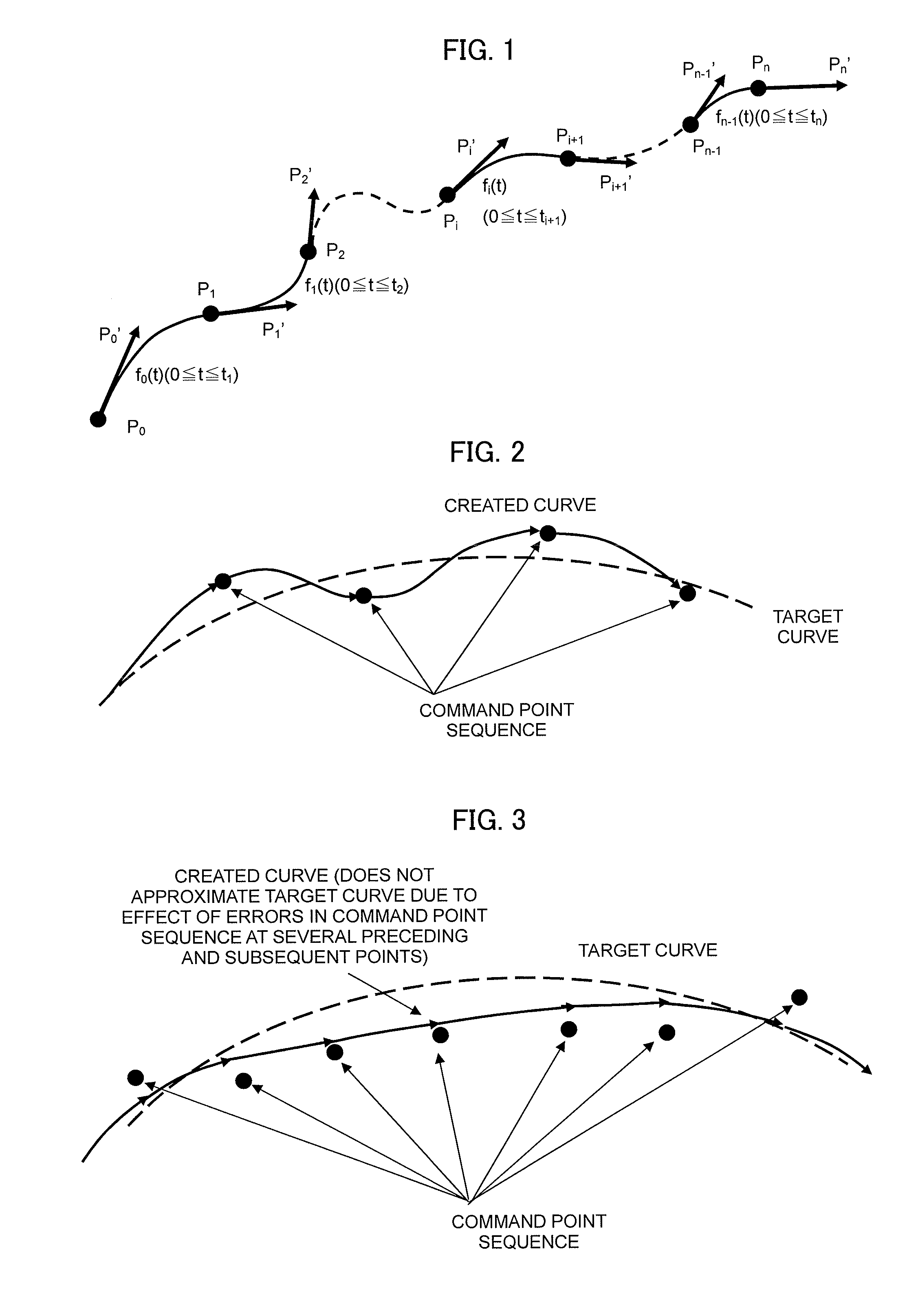
[0060]Processes performed by a segment curve creating unit that is a critical part of the present invention will now be outlined. More specifically, in a case where a given point Ps(k) of a command point sequence P0, P1, P2, . . . , Pn having P0 as a starting point and Pn as an ending point and a first-derivative vector Ps(k)′ at the point Ps(k) have already been determined, a method of creating a cubic function for a segment curve that is a cubic curve having Ps(k) as a starting point will be outlined. Subscripts in the command point sequence P0, P1, P2, . . . , Pn represent numbers of command points.
[0061]k denotes the number of a segment curve to be created. k is incremented per segment curve by one so that k=0 for a first segment curve starting at P0, k=1 for a next segment curve, and so on. s(k) denotes the number of a command point of a segmen...
second embodiment
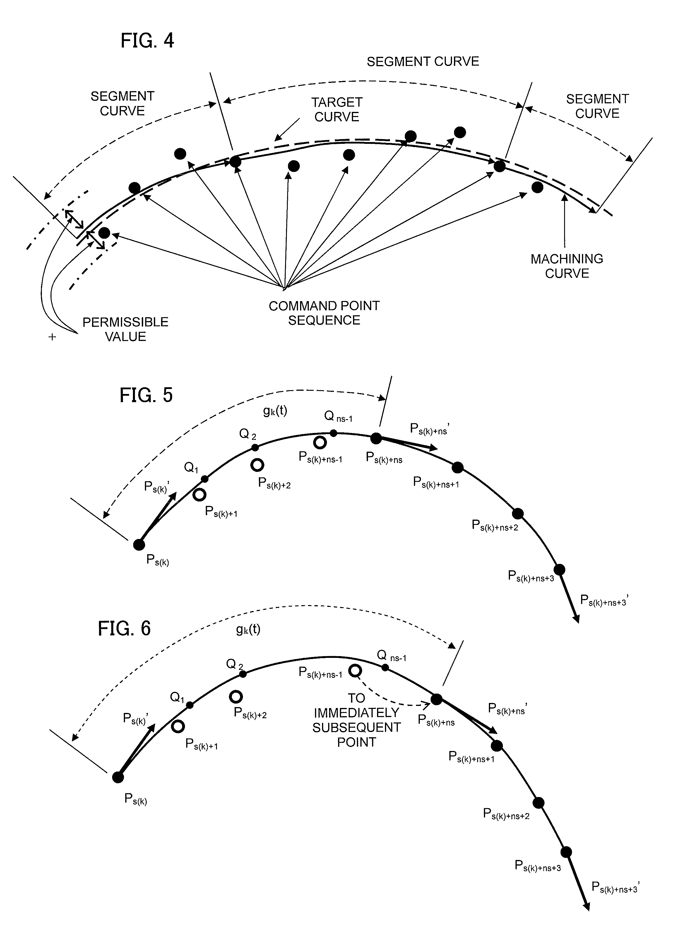
[0067]Moreover, while the first-derivative vector Ps(k)+ns+3′ at Ps(k)+ns+3 is used in this case, as described earlier in “ Curve creation, 1-1”, other conditions (second-derivative vector Ps(k)+ns+3″=0) can be adopted (to be described in the second embodiment).[0068][4] Create Expression (7) below by applying Expression (1) above to Ps(k), Ps(k)+ns, Ps(k)+ns+1, Ps(k)+ns+2, Ps(k)+ns+3, Ps(k)′, Ps(k)+ns′, Ps(k)+ns+′, Ps(k)+ns+2′, and Ps(k)+ns+3′. Meanwhile, Ps(k)+ns′ can be determined with Expression (8-1) below which corresponds to Expression (3) above.
[10000t22(t1+t2)t1000t32(t2+t3)t2000t42(t3+t4)t300001][Ps(k)′Ps(k)+ns′Ps(k)+ns+1′Ps(k)+ns+2′Ps(k)+ns+3′]= [Ps(k)′3t1t2(t12(Ps(k)+ns+1-Ps(k)+ns)+t22(Ps(k)+ns-Ps(k)))3t2t3(ts2(Ps(k)+ns+2-Ps(k)+ns+1)+t32(Ps(k)+ns+1-Ps(k)+ns))3t3t4(t32(Ps(k)+ns+3-Ps(k)+ns+2)+t42(Ps(k)+ns+2-Ps(k)+ns+1))Ps(k)+ns+3′](7)[Ps(k)′Ps(k)+ns′Ps(k)+ns+1′Ps(k)+ns+2′Ps(k)+ns+3′]=[10000t22(t1+t2)t1000t32(t2+t3)t2000t42(t3+t4)t300001]-1* [Ps(k)′3t1t2(t12(Ps(k)+ns+1-Ps(k...
third embodiment
[0131]Next, a numerical controller with a machining curve creating function according to the present invention will be described.
[0132]While a point sequence of command points that are commanded by a machining program has been adopted as a command point sequence in the first and second embodiments, a point sequence produced by performing smoothing on a point sequence of command points that are commanded by a machining program is adopted as the command point sequence in the present third embodiment. Techniques for smoothing are conventional art and the present embodiment combines such smoothing techniques with the present invention.
[0133]For example, a simple smoothing method is as follows. With respect to an original point sequence P1, . . . , Pn−1 extracted from a command point sequence commanded by a machining program by excluding a starting point P0 and an ending point Pn thereof, smoothing which averages Pi and two preceding and subsequent points thereof (Pi−1 and Pi+1) is perfo...
PUM
 Abstract
Description
Claims
Application Information
 - R&D
- Intellectual Property
- Life Sciences
- Materials
- Tech Scout
- Unparalleled Data Quality
- Higher Quality Content
- 60% Fewer Hallucinations
Browse by: Latest US Patents, China's latest patents, Technical Efficacy Thesaurus, Application Domain, Technology Topic, Popular Technical Reports.
© 2025 PatSnap. All rights reserved.Legal|Privacy policy|Modern Slavery Act Transparency Statement|Sitemap|About US| Contact US: help@patsnap.com