
Milking system, and a method for operating a milking system

a technology of a milking system and a filter element, which is applied in the field of milking system, can solve the problems of not being able to replace the filter element, the user is difficult to know whether the filter element needs to be replaced or has recently been replaced, and it is difficult to know which filter element needs to be replaced or replaced

Active Publication Date: 2013-08-22
DELAVAL HLDG AB
View PDF8 Cites 4 Cited by
  • Summary
  • Abstract
  • Description
  • Claims
  • Application Information

AI Technical Summary

Benefits of technology

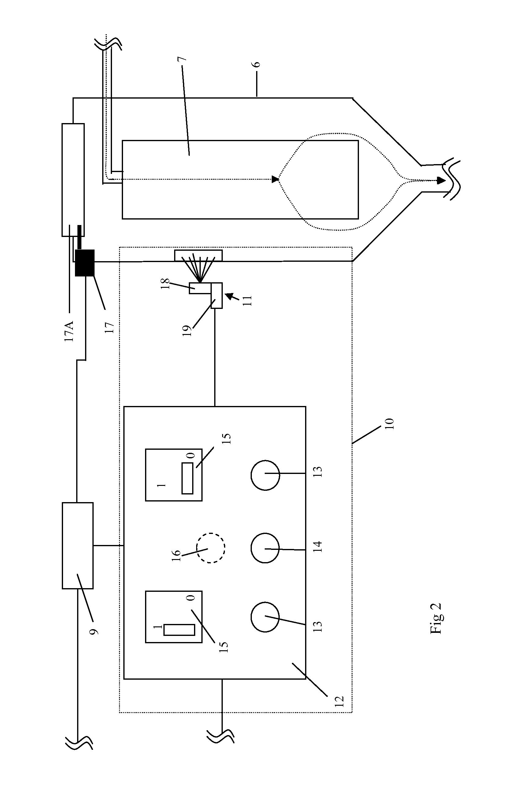
The present invention provides a way for users to easily determine when a filter needs to be replaced in a milking system. The indication device can sense various parameters, like time of use, light absorption, pressure difference, or amount of milk passed through, to determine when the filter is getting dirty and needs replacement. This helps to prevent unnecessary replacement and saves time and money. The indication device can also include a user panel and a mechanical lock to control access to the filter and prevent contamination by microorganisms. The method also reduces the risk of contamination and saves resources. Overall, this invention provides a reliable and efficient way to take care of the filter in a milking system.

Problems solved by technology

One problem with the known milking systems is that it is difficult for the user to know whether a filter element needs to be replaced or has recently been replaced.
In case of two filter devices, it can be difficult to know which of the filter elements needs to be replaced or which of them has been replaced.
It is also not possible to replace the filter element during the cleaning operation when the cleaning liquid is circulating in the transport line and thus through the filter element.

Method used


Image

  • Milking system, and a method for operating a milking system
  • Milking system, and a method for operating a milking system

Examples


Embodiment Construction

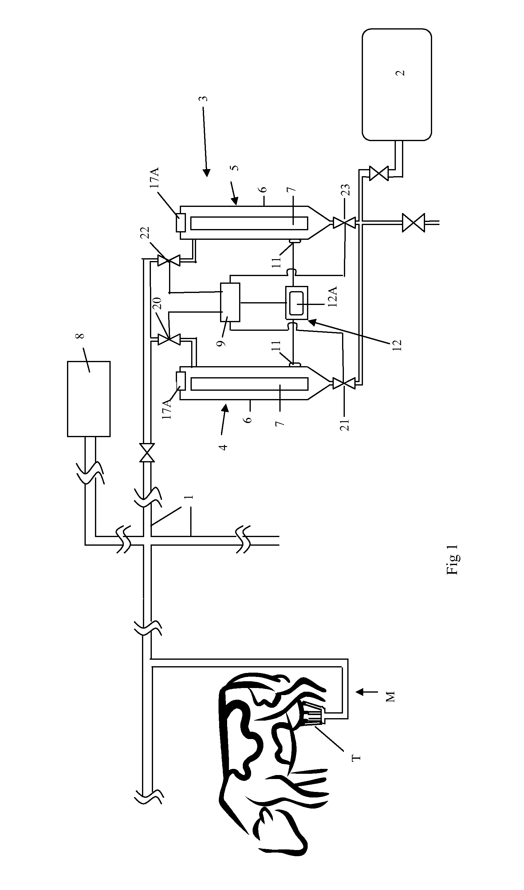
[0025]FIG. 1 discloses a milking system with a milking member M comprising a claw and a number of teatcups T, such as four teatcups T. In the milking system a large number of milking members M may be provided for milking of animals several times a day. The milk from the milking members M is conveyed via a transport line 1 to a milk tank 2. All the milk passes a milk filter unit 3 provided to filter milk residues, dirt particles such as fibres, hairs and dung particles from the milk. The milk filter unit 3 is provided on the transport line 1 and comprises at least a first filter device 4 and a second filter device 5 as shown in FIG. 1.

[0026]The first and second filter devices 4, 5 are preferably arranged in parallel to each other. Each filter device 4 comprises a filter container 6 and a filter element 7. The milk filter unit 3 may also comprise more than two filter devices, see for instance WO02 / 074070.

[0027]The milking system also comprises a cleaning equipment 8, which is connecte...


PUM


Abstract

A milking system includes a milking member for extracting milk from an animal, a transport line, a milk tank, a milk filter unit for filtering the milk with a first filter device and a second filter device, each including a filter container and a filter element, and a valve arrangement to convey milk through the devices, where the valve arrangement communicates with a control unit. The milking system further includes an indication device generating an indication to a user when any one of the filter elements needs to be replaced, which filter of the first and second filter device needs to be replaced, and when the filter element indicated to need to be replaced is accessible for replacement. A method for operating and cleaning the milking system is also provided.

Description

TECHNICAL FIELD OF THE INVENTION[0001]The present invention refers generally to a milking system for extracting milk from animals that have been milked. Specifically, the invention refers to a milking system according to the preamble of claim 1, see EP-A-1 559 314. The present invention further relates to a method for operating a milking system according to the preamble of claim 11.BACKGROUND OF THE INVENTION AND PRIOR ART[0002]In large milking systems a large number of milking members are connected to the same milk tank for receiving and storing the milk from the different milking members. The milk from the different milking members is conveyed to the milk tank via a transport line. All milk passes through a milk filter unit before reaching the milk tank. The filter element or elements of the milk filter unit has to be replaced regularly, typically three times a day. It is preferred to replace the filter element just before the cleaning operation so that the cleaning operation can ...

Claims


Application Information

Patent Timeline
Patent Type & Authority Applications(United States)
IPC IPC(8): A01J11/06A01J7/02
CPCA01J11/06A01J7/022A01J5/0134
Inventor BOSMA, EPKEPERSSON, STAFFAN
Owner DELAVAL HLDG AB
Learn More