
Extra-articular implantable mechanical energy absorbing assemblies having two deflecting members and methods

a technology of mechanical energy absorption and assembly, which is applied in the field of system and method of treating, tissue of the body, can solve the problems of cell death, morphological and cellular damage, subsequent inflammation, etc., and achieve the effect of relieving at least a portion of the load resultant and reducing the load

Inactive Publication Date: 2013-08-08
MOXIMED INC
View PDF3 Cites 15 Cited by
  • Summary
  • Abstract
  • Description
  • Claims
  • Application Information

AI Technical Summary

Benefits of technology

The patent describes an assembly for treating an anatomical joint that reduces load on the joint by flexing and absorbing energy from forces applied by members of the joint. This results in a reduction of pain and improved mobility for the patient. The assembly is implanted and includes a first flex member attached to one anatomical member and a second flex member attached to the other anatomical member. The method involves flexing the first and second flex members to transiently vary the load between the anatomical members.

Problems solved by technology

Recent experimental studies further indicate that excessive, repetitive loading may induce cell death, and cause morphological and cellular damage, as seen in degenerative joint disease (Lucchinetti et al., 2002 and Sauerland et al., 2003).
Gouty arthritis is caused by deposition of uric acid crystals in the joint that results in subsequent inflammation.
Unfortunately, all arthritides feature pain.
As the bone surfaces become less well protected by cartilage, the patient experiences pain upon weight bearing, including walking and standing.
Due to decreased movement because of the pain, regional muscles may atrophy, and ligaments may become more lax.
The main symptoms of osteoarthritis is chronic pain, causing loss of mobility and often stiffness.
OA can cause a crackling noise (called “crepitus”) when the affected anatomical joint is moved or touched, and patients may experience muscle spasm and contractions in the tendons.
Humid weather increases the pain in many patients.
However, it was concluded that such techniques do not presently predictably restore a durable articular surface to an osteoarthritic joint.
Such procedures are a last resort treatment as they are highly invasive and require substantial periods of recovery.
These procedures are also characterized by relatively long recovery times and are highly invasive procedures.
The currently available therapies are not condro-protective.
However, HTO does not address ligamentous instability—only mechanical alignment.
HTO is associated with good early results, but results typically deteriorate over time.
Further, as with most materials that experience structural loads, particularly cyclic structural loads, both hone and cartilage begin to show signs of failure at loads that are below their ultimate strength.
There is also a level of load at which the skeleton will fail catastrophically.
Accordingly, it has been concluded that the treatment of osteoarthritis and other conditions is severely hampered when a surgeon is not able to precisely control and prescribe the levels of anatomical joint load.
Various of these approaches have had some success in alleviating pain but stiller from patient compliance or lack an ability to facilitate and support the natural motion and function of the diseased anatomical joint.
Therefore, mechanical approaches to treating osteoarthritis have had limited applications.
That is, in addition to addressing loads at an anatomical joint and anatomical joint movement, there has not been an approach which also acknowledges the dampening and energy absorption functions of the anatomy, and taking a minimally invasive approach in implementing solutions.

Method used


Image

  • Extra-articular implantable mechanical energy absorbing assemblies having two deflecting members and methods
  • Extra-articular implantable mechanical energy absorbing assemblies having two deflecting members and methods
  • Extra-articular implantable mechanical energy absorbing assemblies having two deflecting members and methods

Examples


Embodiment Construction

[0076]Before the present devices and methods are described, it is to be understood that this invention is not limited to particular embodiments described, as such may, of course, vary. It is also to be understood that the terminology used herein is for the purpose of describing particular embodiments only, and is not intended to be limiting, since the scope of the present invention will be limited only by the appended claims.

[0077]Where a range of values is provided, it is understood that each intervening value, to the tenth of the unit of the lower limit, unless the context clearly dictates otherwise, between the upper and lower limits of that range is also specifically disclosed. Each smaller range between any stated value or intervening, value in a stated range and any other stated or intervening value in that stated range is encompassed within the invention. The upper and lower limits of these smaller ranges ma independently be included or excluded in the range, and each range w...


PUM


Abstract

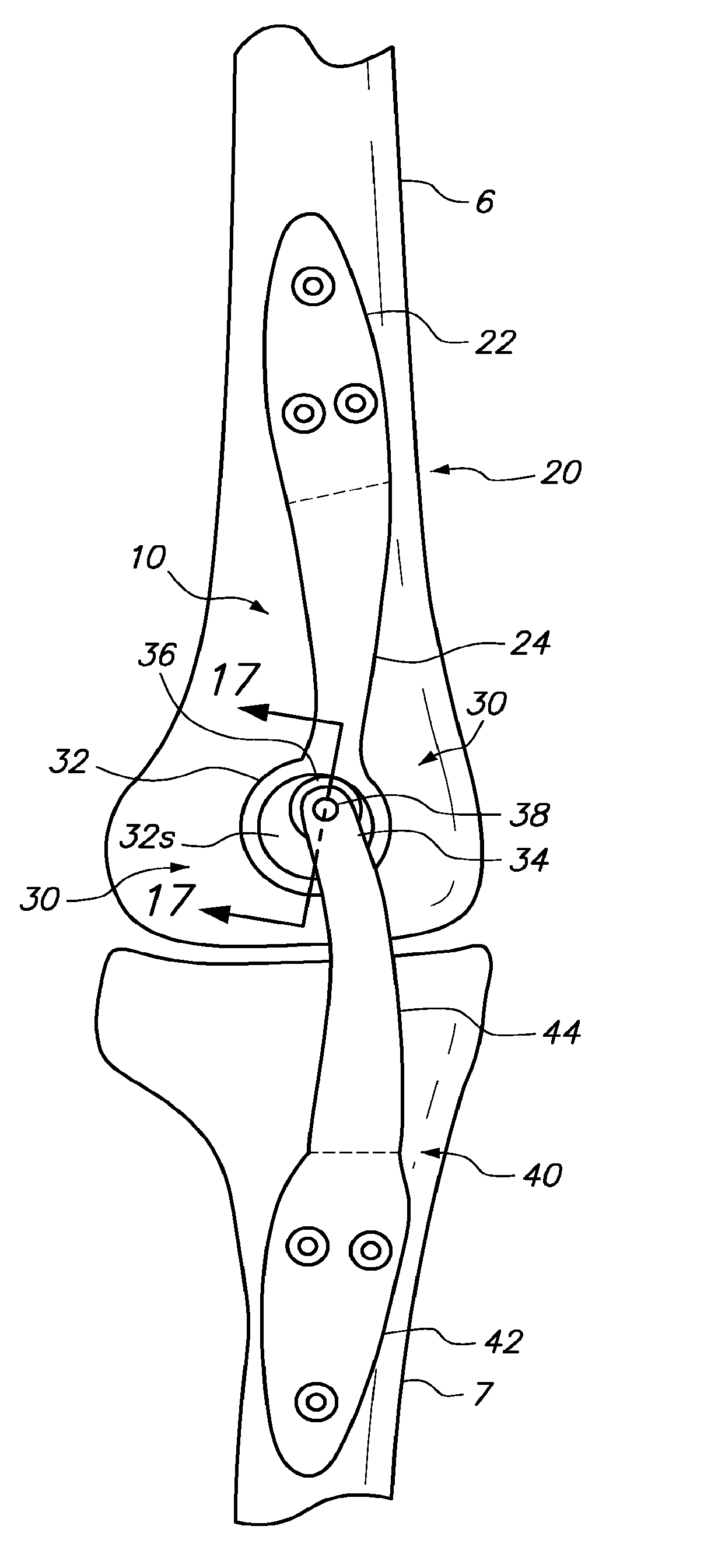
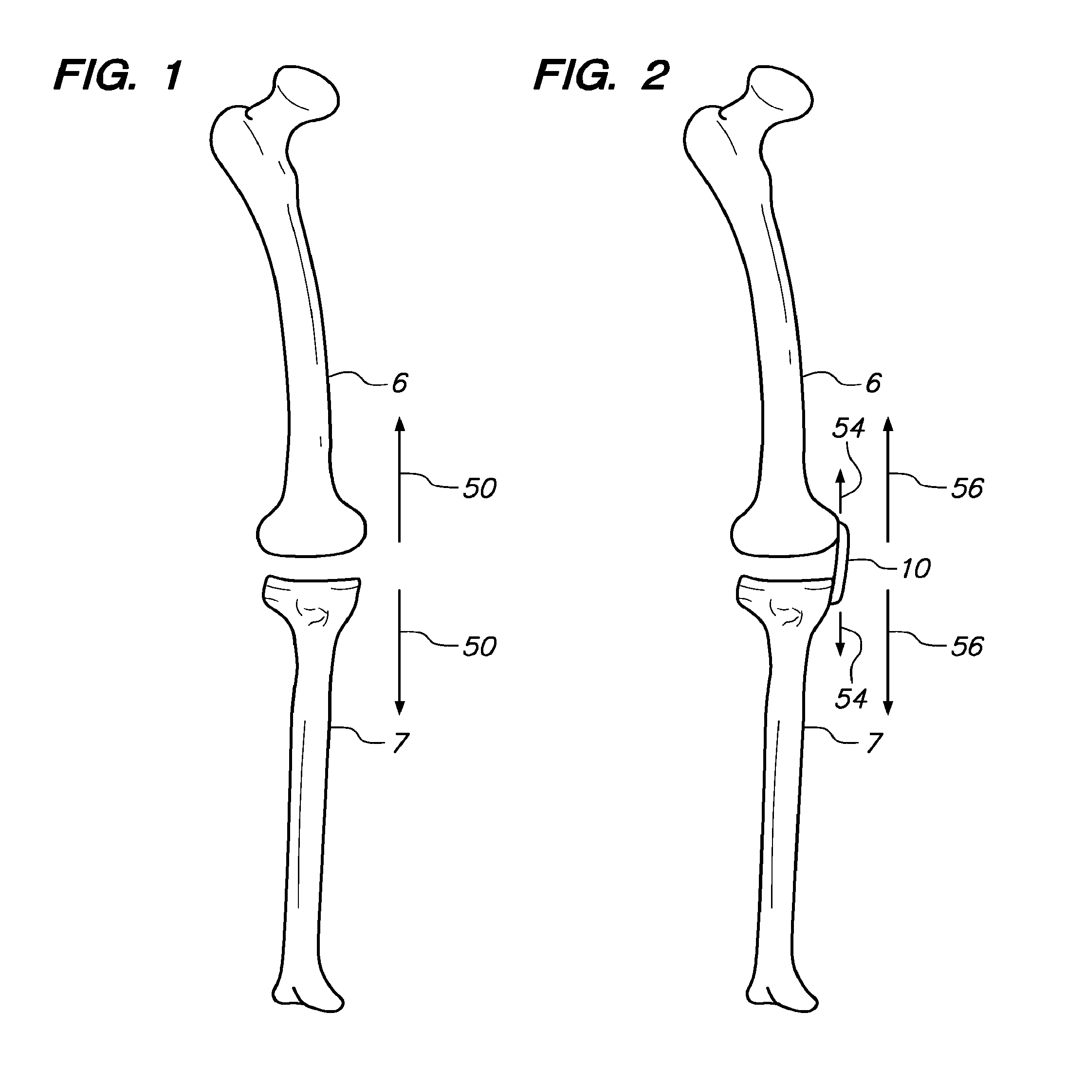
Implantable assemblies for manipulating energy transferred by members defining an anatomical joint, and methods of implanting and using. The members of the anatomical joint collectively define a path of motion. An assembly includes a first component configured to be attached to a first member of the anatomical joint; a second component configured to be attached to a second member of the anatomical joint; and a joint joining the first and second components. The first component includes a first flex member and the second component includes a second flex member. The first and second flex members are configured to flex to absorb energy transferred by the members of the anatomical joint.

Description

FIELD OF THE INVENTION[0001]The present invention is directed towards systems and methods for treating, tissue of a body and more particularly, towards approaches designed to reduce mechanical energy transferred between members forming an anatomical joint.BACKGROUND OF THE INVENTION[0002]An anatomical joint is the location at which two or more bones make contact. They are constructed to allow movement and provide mechanical support, and are classified structurally and functionally. Structural classification is determined by how the bones connect to each other, while functional classification is determined by the degree of movement between the articulating bones. In practice, there is significant overlap between the two types of classifications.[0003]There are three structural classifications of anatomical joints, namely fibrous or immovable anatomical joints, cartilaginous anatomical joints and synovial anatomical joints. Fibrous / Immovable bones are connected by dense connective tis...

Claims


Application Information

Patent Timeline
Patent Type & Authority Applications(United States)
IPC IPC(8): A61F2/38
CPCA61B17/56A61B2017/567A61F2/0811A61F2/38A61F2/3886A61F2002/0864A61F2002/0888A61F2/384A61F2002/0829
Inventor SLONE, CLINTON N.CLIFFORD, ANTON G.MINO, TORUREGALA, ALAN C.
Owner MOXIMED INC
Learn More