
Tire For Center Pivot Irrigation

a technology of pivot irrigation and tire, which is applied in the field of tires, can solve the problems of tire sinking deeply into the ground, affecting the operation of the system,

Active Publication Date: 2013-08-01
MACH II TIRE CO LLC
View PDF6 Cites 5 Cited by
  • Summary
  • Abstract
  • Description
  • Claims
  • Application Information

AI Technical Summary

Benefits of technology

This patent relates to a non-pneumatic tire for a center pivot irrigation system that uses half-tires connected by cleats and connectors. The half-tires have transverse traction cleats and connecting cleats with a ratio of cleat width to edge width of at least about 1.25:1. The cleats are tapered in width, with a narrower edge to improve grip. The tire is formed by heating a mold and then cooling it with rotation. The technical effect is a non-pneumatic tire that improves grip and stability for a center pivot irrigation system.

Problems solved by technology

The weight supported by each tower is substantial causing the tires to sink deeply into the ground.
As the tires roll across muddy soil, the tires tend to push mud to the sides and front of the tire.
The accumulated mud pushed to the front of the tire can eventually build up to the point that the tire can no longer advance.
Rubber tires are also subject to damage or wear causing a flat tire, which also shuts down the system until the flat tire is repaired or replaced.

Method used


Image

  • Tire For Center Pivot Irrigation
  • Tire For Center Pivot Irrigation
  • Tire For Center Pivot Irrigation

Examples


Embodiment Construction

[0032]While the invention will be described in connection with the preferred embodiment, it will be understood that it is not intended to limit the invention to this embodiment. On the contrary, it is intended to cover all alternatives, modifications, and equivalents as may be included within the spirit and scope of the invention.

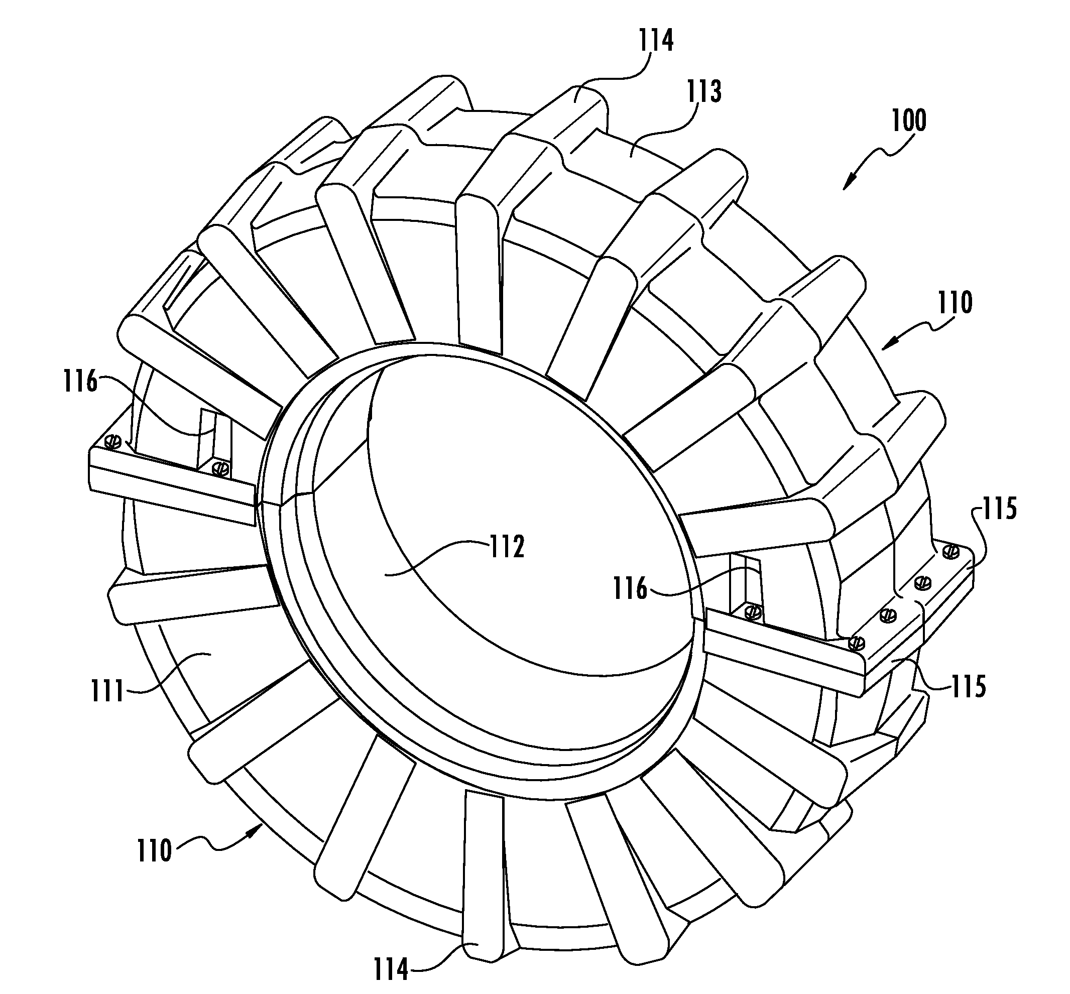
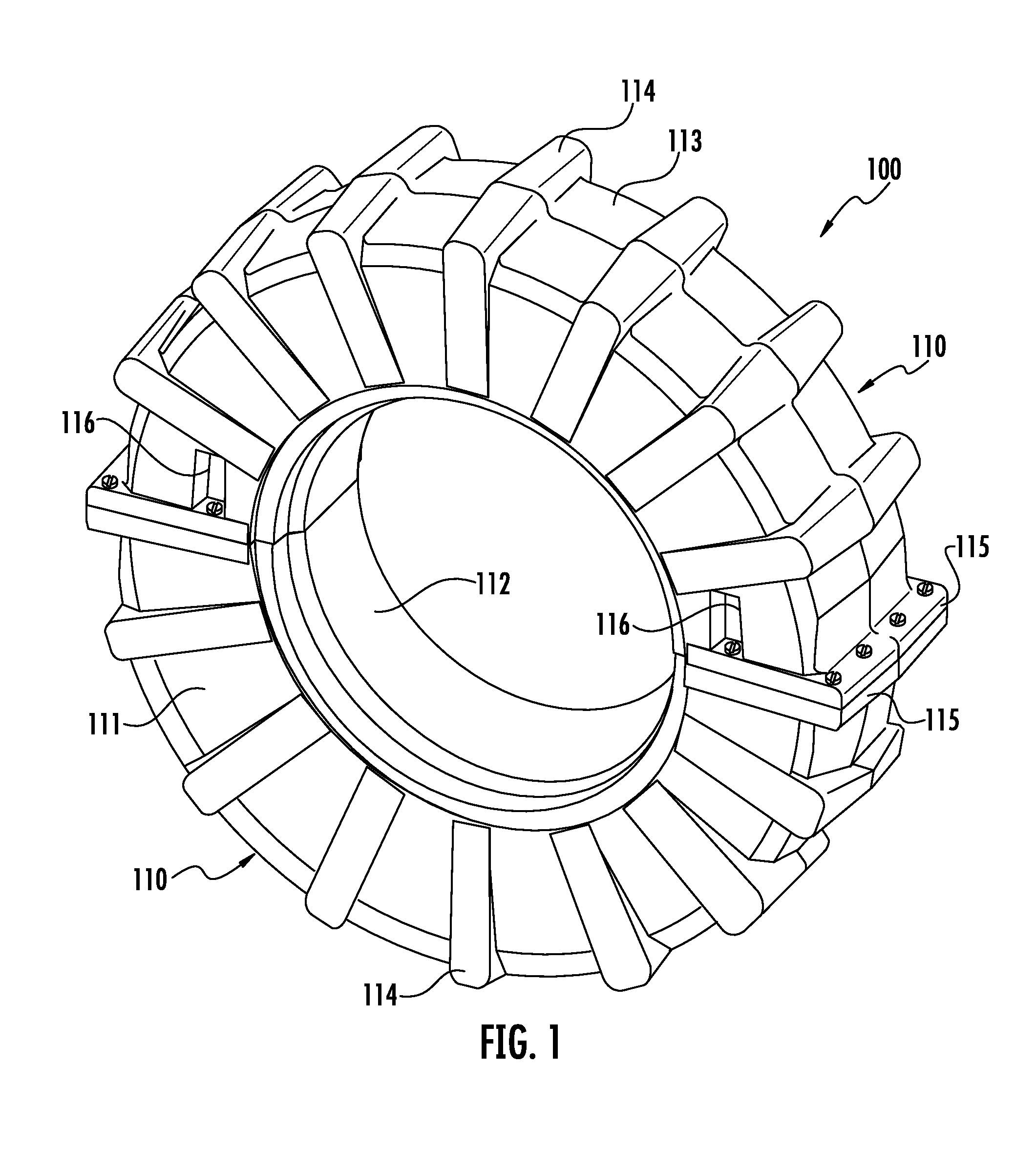
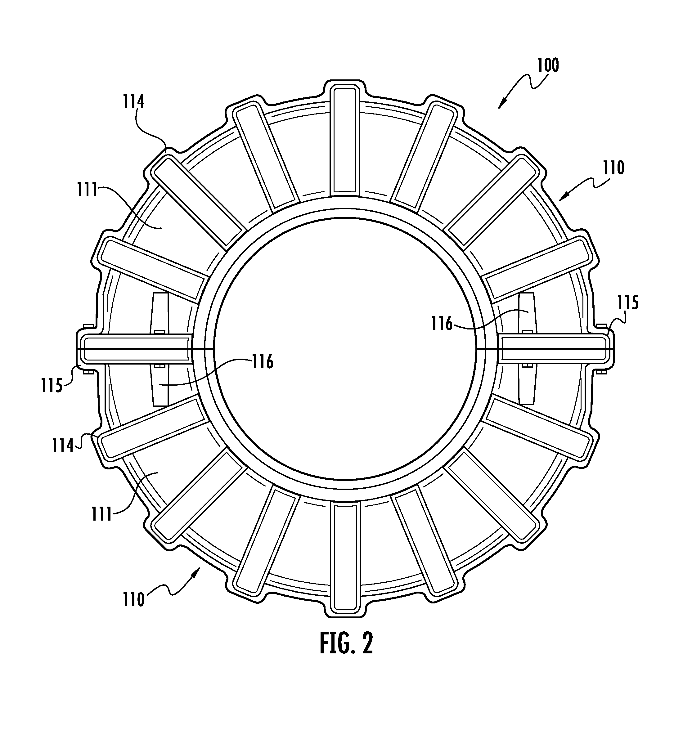
[0033]The present disclosure relates to a non-pneumatic rotationally molded two-piece tire for center pivot irrigation systems. In various exemplary embodiments, the disclosed non-pneumatic tire 100 comprises two substantially semicircular pieces that are securely connected together to form a tire.

[0034]In various exemplary embodiments, as shown in FIG. 1, the disclosed non-pneumatic tire 100 comprises two halves 110. As illustrated in the exemplary embodiment of FIGS. 2-4, each half-tire 110 comprises a substantially semi-circular hollow piece defined by two sidewalls 111, an inner circumferential wall 112, and an outer circumferential wall 113. In various...


PUM


Abstract

An exemplary embodiment relates to a non-pneumatic tire for a center pivot irrigation system comprising two arcuate half-tire segments, the segments having two sidewalls connected by an outer circumferential wall and an inner circumferential wall; a plurality of transverse traction cleats circumferentially spaced on the outer circumferential wall extending between the side walls, the cleats having a rounded tip; a pair of connecting cleats at the ends of the half-tire segments having a plurality of apertures adapted for use in connecting the two arcuate half-tire segments; and a plurality of connectors adapted for insertion into the apertures wherein the cleats are tapered in width having a ratio of the center width of the cleat to the edge width of the cleat of at least about 1.25:1.

Description

NON-PNEUMATIC PRIORITY[0001]This application claims priority to U.S. Provisional Application 61 / 591,138 filed on Jan. 26, 2012, which is incorporated herein by reference in its entirety.BACKGROUND[0002]1. Field of the Invention[0003]The present disclosure relates to tires. More particularly, it relates to a non-pneumatic rotationally molded tire for center pivot irrigations systems.[0004]2. Related Art[0005]In center pivot irrigation systems, water from a centrally located source (e.g., a well) is directed along a long boom pipe to the field. The boom pivots around the center point on spaced apart towers, which support the boom. The towers are generally supported by large pneumatic rubber tires similar to conventional tractor tires. The weight supported by each tower is substantial causing the tires to sink deeply into the ground. As the tires roll across muddy soil, the tires tend to push mud to the sides and front of the tire. The accumulated mud pushed to the front of the tire ca...

Claims


Application Information

Patent Timeline
IPC IPC(8): B60C7/08
CPCY10T152/10342B60C7/08
Inventor SELJAN, SCOTT P.
Owner MACH II TIRE CO LLC
Learn More