
Anchor driver

a technology for installing anchors and drivers, applied in the field of tools for installing anchors in concrete, can solve problems such as inability to summariz

Active Publication Date: 2013-06-27
PRUNEAN DAVID C
View PDF11 Cites 37 Cited by
  • Summary
  • Abstract
  • Description
  • Claims
  • Application Information

AI Technical Summary

Benefits of technology

The patent text describes two types of anchor drivers that can be used in a hammer drill. These drivers eliminate the need for manual labor and make the installation process faster and more efficient. The technical effects of this innovation are improved speed and efficiency in installing anchors.

Problems solved by technology

Moreover, this Summary is not intended for use as an aid in determining the scope of the claimed subject matter.

Method used


Image

  • Anchor driver
  • Anchor driver
  • Anchor driver

Examples


Embodiment Construction

[0030]What follows is a detailed description of the preferred embodiments of the invention in which the invention may be practiced. Reference will be made to the attached drawings, and the information included in the drawings is part of this detailed description. The specific preferred embodiments of the invention, which will be described herein, are presented for exemplification purposes, and not for limitation purposes. It should be understood that structural and / or logical modifications could be made by someone of ordinary skills in the art without departing from the scope of the invention.

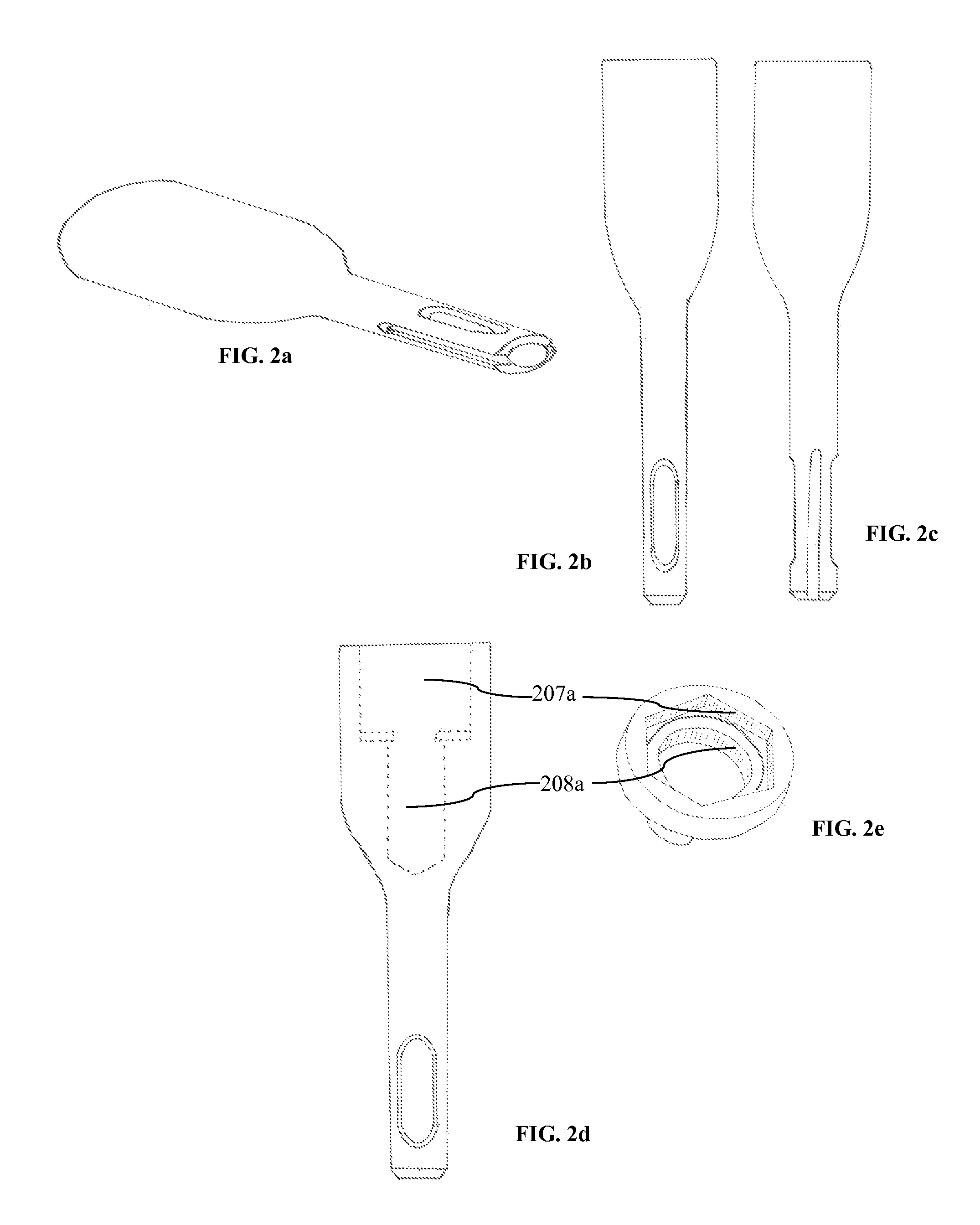
[0031]Referring to FIG. 1, perspective views of a wedge anchor 101 (prior art), and of an adjustable wedge anchor driver 102 according to one embodiment are shown. The wedge anchor 101 is an example of a typical wedge anchor known in the art. The adjustable wedge anchor driver 102 is one of the embodiments of the invention disclosed herein. The adjustable wedge anchor driver 102 essentially con...


PUM


Abstract

A wedge anchor driver comprising: a first member having a first opening configured to fit onto the nut of a wedge anchor and a second opening configured to receive a predetermined length of the outer end of the wedge anchor's bolt; and a second member associated with the first member, wherein the second member's distal end is configured to fit, and be lockable, into the chuck of a hammer drill, such that, after the wedge anchor driver is locked into the chuck of the hammer drill, a user can drive the wedge anchor into a corresponding hole with the hammer drill in hammer mode and then tighten the nut of the wedge anchor by switching the hammer drill from hammer mode to drill mode.

Description

CROSS-REFERENCE TO RELATED APPLICATIONS[0001]This application claims the benefit of U.S. Provisional Application No. 61 / 579,765, filed Dec. 23, 2011, which is hereby incorporated by reference, to the extent that it is not conflicting with the present application.STATEMENT REGARDING FEDERALLY SPONSORED RESEARCH OR DEVELOPMENT[0002]Not ApplicableREFERENCE TO SEQUENCE LISTING, A TABLE, OR A COMPUTER PROGRAM LISTING COMPACT DISC APPENDIX[0003]Not ApplicableBACKGROUND OF THE INVENTION[0004]1. Field of the Invention[0005]The invention relates generally to the tool technology and more particularly to tools for installing anchors in concrete.[0006]2. Description of the Related Art[0007]Currently, with the existing tools and methods, installing anchors in concrete is a slow, labor intensive and costly process, as it involves a significant amount of manual labor.[0008]The process used to fasten anchors to concrete has basically remained unchanged over the years. Although there are epoxy / chemi...

Claims


Application Information

Patent Timeline
IPC IPC(8): B25B21/00B25B23/00B25D17/02
CPCB25B21/007B25D17/02Y10T279/3418B25B31/00B25B23/00
Inventor PRUNEAN, DAVID C.
Owner PRUNEAN DAVID C
Learn More