Speed activated closure assembly in a tubular and method thereof

a technology of activated closure and tubular, which is applied in the direction of tubing catchers, drilling pipes, borehole/well accessories, etc., can solve the problems of affecting the service life of the cable, the loss of time spent retrieving dropped objects, and the inconvenience of handling

Active Publication Date: 2013-06-20
BAKER HUGHES INC
View PDF5 Cites 20 Cited by
  • Summary
  • Abstract
  • Description
  • Claims
  • Application Information

AI Technical Summary

Benefits of technology

[0004]A tubular closure assembly responsive to speed or velocity of an object, the tubular closure assembly includes at least one sensor in operable communication with an interior of a tubular, the at least one sensor sensing an object passing a first point and then a second point within the tubular; a processor receiving an output from the at least one sensor and calculating speed of the object from the first point to the second point; a control panel receiving information from the processor; and, a closure system movable between an open condition and a closed condition, and activatable to the closed condition by the control panel in response to the object moving from the first point to the second point at speed faster than a preset value or at a velocity outside a preset range.

Problems solved by technology

As tools are taken out through the riser pipe or introduced into the borehole through the riser pipe, some oil field operators have experienced a loss of tools and other equipment downhole when the tools and equipment are accidentally dropped, resulting in a loss of time trying to retrieve such dropped objects.
Additionally, considerable expense may be suffered if the dropped object cannot be retrieved.
It has been previously proposed to extrapolate a speed of a cable dropped into a well by monitoring rotation of wheels that pass the cable into the well or by monitoring the cable tension, however this approach requires direct contact with the cable and is limited to spooled devices.
Another extremely undesirable experience that needs to be prevented in the drilling and completion industry is a blowout.
It has been previously proposed to employ slip rams of a blowout preventer to assist in the prevention of lost tubulars and tools downhole during their removal process, however this approach requires contact with the tubular or tool, is not based on the speed of the tubulars, and is limited to use during removal as it does not allow introduction into the well.

Method used


Image

  • Speed activated closure assembly in a tubular and method thereof
  • Speed activated closure assembly in a tubular and method thereof
  • Speed activated closure assembly in a tubular and method thereof

Examples


Embodiment Construction

[0016]A detailed description of one or more embodiments of the disclosed apparatus and method are presented herein by way of exemplification and not limitation with reference to the Figures.

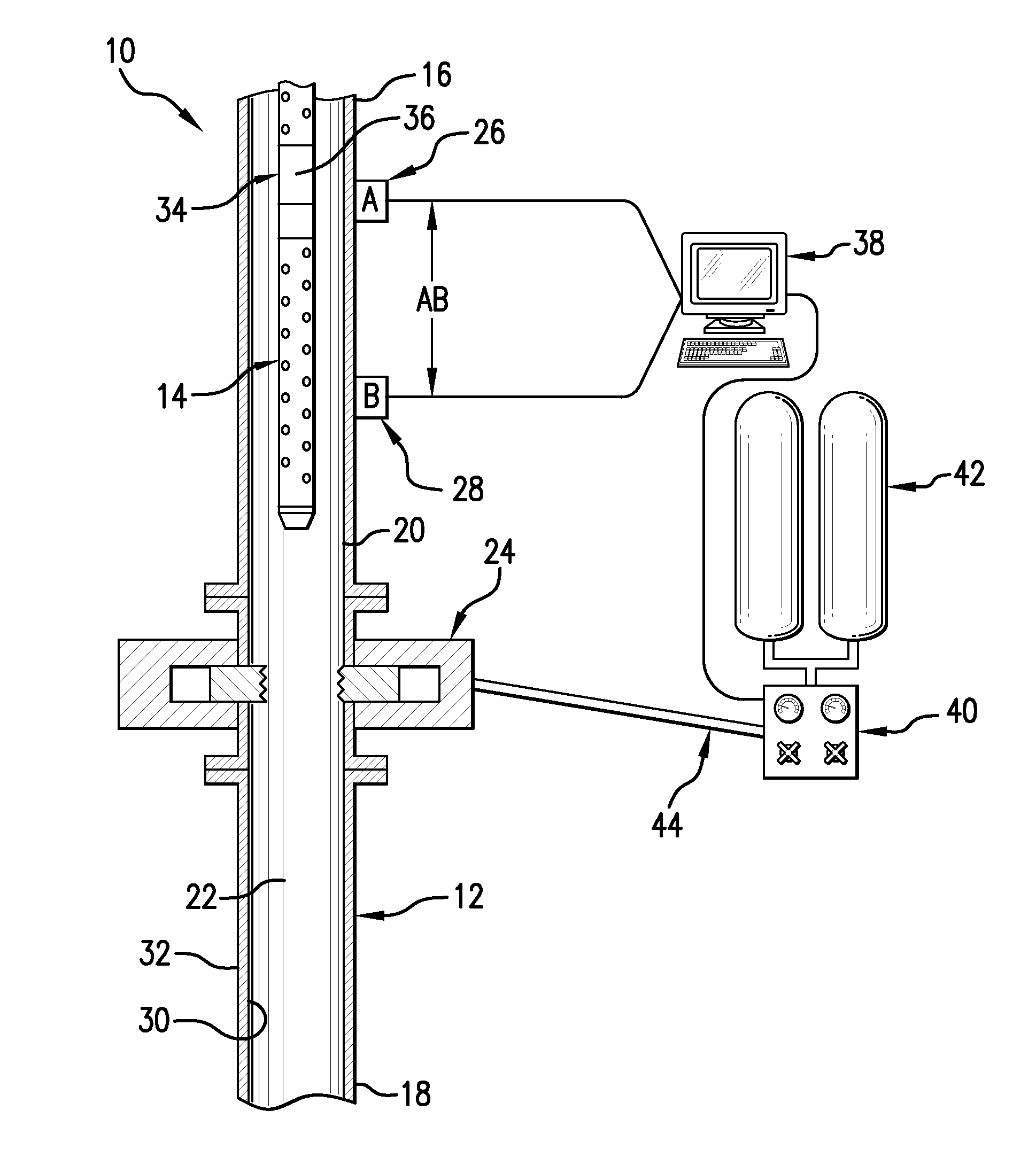
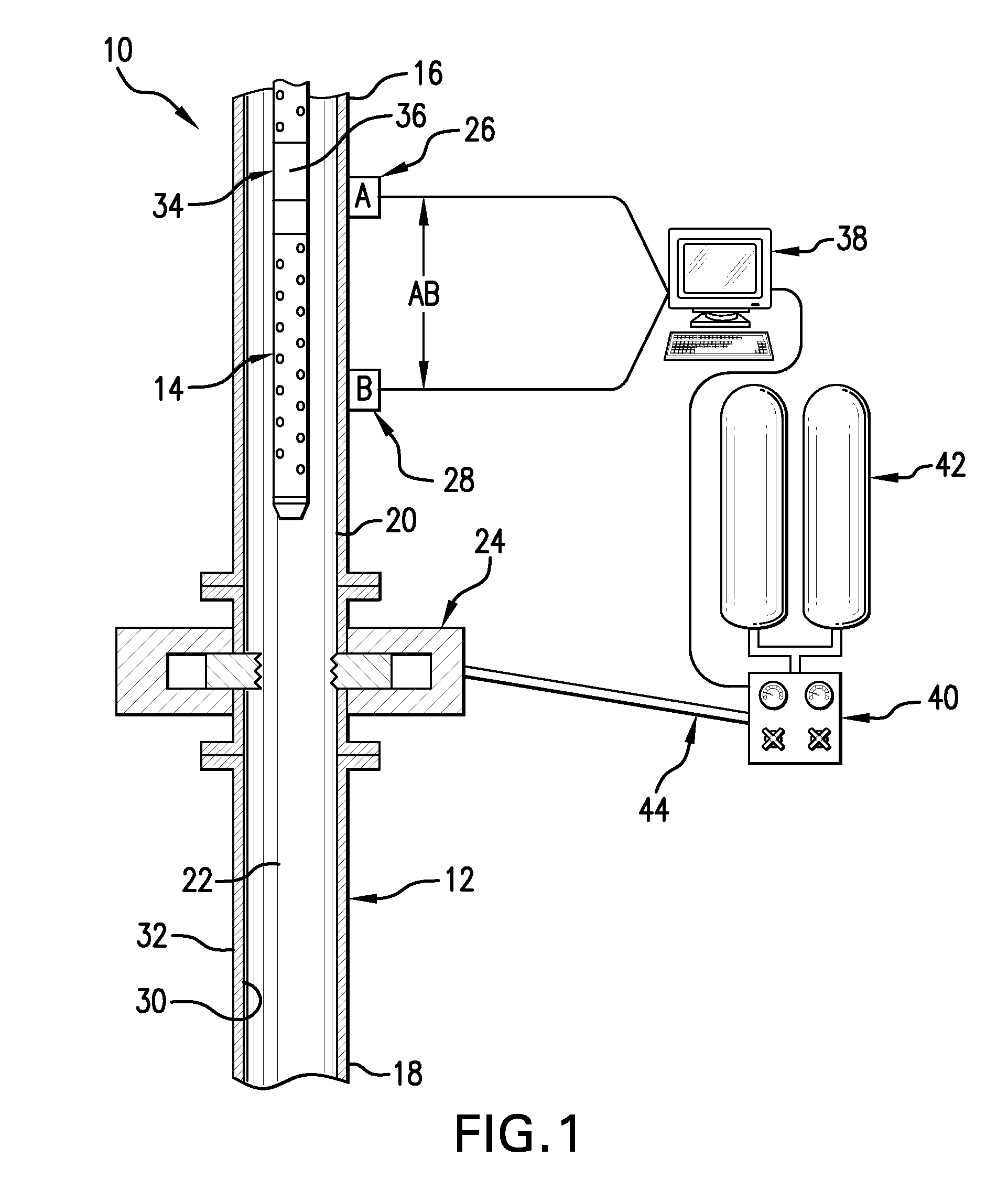
[0017]As shown in FIG. 1, in one exemplary embodiment, a speed activated closure assembly 10 includes a tubular 12. Although the closure assembly 10 may be incorporated with any tubular along the length of a borehole, the closure assembly 10 is most advantageously incorporated within a riser, at an uphole end of the borehole. Incorporation within a riser prevents a dropped object, such as object 14, from traveling downhole further into the borehole, simplifying the retrieval of the dropped object 14. However, the closure assembly 10 is also installable further downhole the borehole, i.e. downhole of a riser, to prevent an object 14, such as a well tool that is in use, from falling further downhole into a casing, sleeve, or other tubular. A plurality of the closure assemblies 10 may be provided at...


PUM


Abstract

A tubular closure assembly responsive to speed or velocity of an object. The tubular closure assembly includes at least one sensor in operable communication with an interior of a tubular. The at least one sensor sensing an object passing a first point and then a second point within the tubular. A processor receiving an output from the at least one sensor and calculating speed of the object from the first point to the second point. A control panel receiving information from the processor and a closure system movable between an open condition and a closed condition. Activatable to the closed condition by the control panel in response to the object moving from the first point to the second point at speed faster than a preset value or at a velocity outside a preset range. Also included is a method of closing a tubular of a borehole.

Description

BACKGROUND[0001]In the drilling and completion industry, the formation of boreholes for the purpose of production or injection of fluid is common The boreholes are used for exploration or extraction of natural resources such as hydrocarbons, oil, gas, water, and CO2 sequestration. A riser pipe may be fitted at the top of the borehole as a guide for a drill stem or as a conductor for drilling fluid. As tools are taken out through the riser pipe or introduced into the borehole through the riser pipe, some oil field operators have experienced a loss of tools and other equipment downhole when the tools and equipment are accidentally dropped, resulting in a loss of time trying to retrieve such dropped objects. Additionally, considerable expense may be suffered if the dropped object cannot be retrieved. It has been previously proposed to extrapolate a speed of a cable dropped into a well by monitoring rotation of wheels that pass the cable into the well or by monitoring the cable tension,...

Claims


Application Information

Patent Timeline
Patent Type & Authority Applications(United States)
IPC IPC(8): E21B33/06E21B33/10E21B47/00
CPCE21B40/00E21B19/12E21B41/0021
Inventor MYERS, WILLIAM D.
Owner BAKER HUGHES INC
Why Eureka
Try Eureka