
Fluid mixing device

Active Publication Date: 2013-05-30
NEC CORP
View PDF1 Cites 0 Cited by
  • Summary
  • Abstract
  • Description
  • Claims
  • Application Information

AI Technical Summary

Benefits of technology

The present invention provides a fluid mixing device that includes a valve to prevent the flow of liquid from one tank to another, improving operability and reliability without the need for high accuracy pressure control. The valve is opened or closed by the liquid in the device, simplifying the connection to external mechanisms and improving productivity and maintainability.

Problems solved by technology

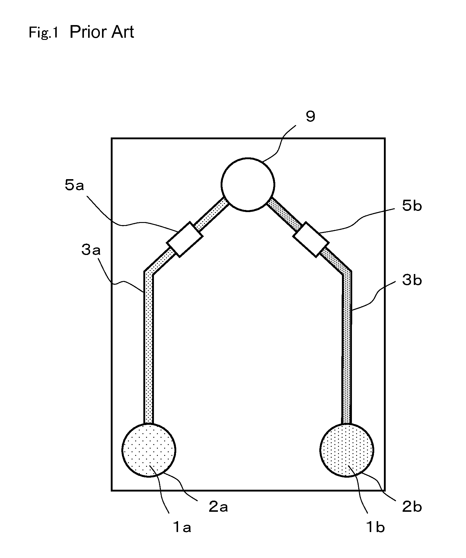
Even if the syringe pump is used, the amount of liquid that is fed and the capacities of the flow channel, the supply tank, and the mixing tank cannot be sufficiently controlled, so that it is surely thought that the amount of liquid that is fed to the mixing tank exceeds the allowance of the mixing tank to thereby cause the flow of the liquid from the mixing tank to the supply tank.
In the related micro chip shown in FIG. 1, in the case where a valve preventing the flow from the mixing tank to the supply tank is constructed by the use of a passive valve, the pressure of first liquid 1a needs to be equal to or more than a flow resistance value of first valve 5a and to be less than a flow resistance value of second valve 5b. In other words, this requires high accuracy pressure control and may reduce the operability of the micro chip.
In other words, there is a possibility that feeding the liquid to mixing tank 9 and preventing the flow of the liquid to the second supply tank 2 are not normally performed to thereby reduce the reliability of the micro chip.
Thus, the connection of the external mechanism to the micro chip is increased to thereby make the handling of the micro chip cumbersome, which may reduce productivity.
Further, since the external mechanism is newly provided, there is also presented a problem in which the maintenance and the inspection of the external mechanism are newly required.

Method used


Image

  • Fluid mixing device
  • Fluid mixing device
  • Fluid mixing device

Examples


Embodiment Construction

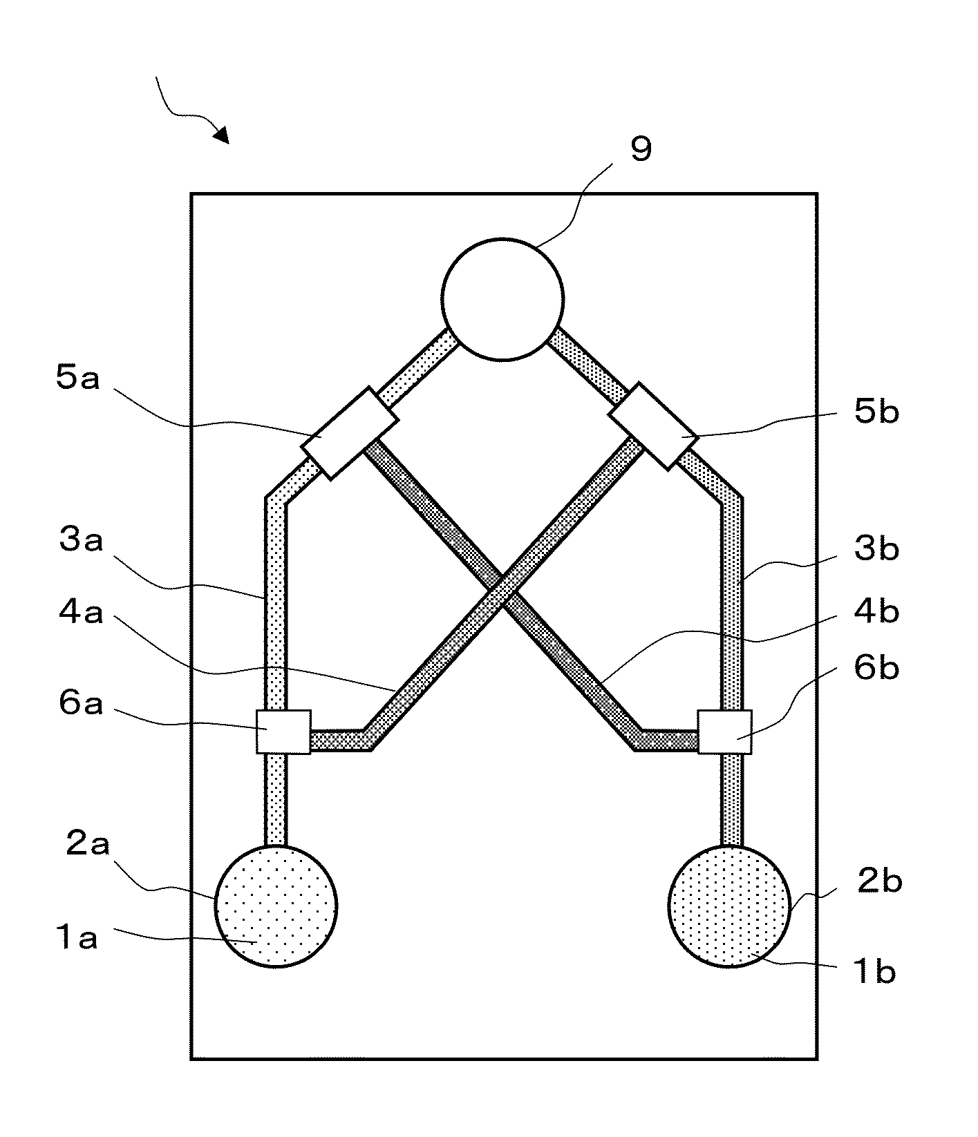
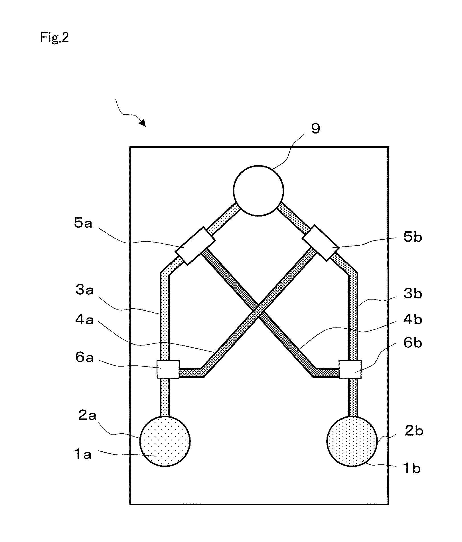
[0040]An exemplary embodiment of the present invention will be described in detail with reference to drawings. FIG. 2 is a schematic view of micro chip 10 in an exemplary embodiment of the present invention. Micro chip 10 is a chip that mixes first liquid 1a such as a sample or a reagent, which is an object to be tested or analyzed, with second liquid 1b, which is different from first liquid 1a, in mixing tank 9. In micro chip 10, first liquid 1a is fed to mixing tank 9 and then second liquid 1b is fed to mixing tank 9.

[0041]Micro chip 10 has first supply tank 2a for supplying first liquid 1a and second supply tank 2b for supplying second liquid 1b. Further, micro chip 10 has first mixing tank flow channel 3a for feeding first liquid 1a from first supply tank 2a to mixing tank 9 and has second mixing tank flow channel 3b connecting second supply tank 2b to mixing tank 9 at a position different from a position where first mixing tank flow channel 3a is provided. First supply tank 2a ...


PUM


Abstract

A fluid mixing device is productive, maintainable and improved in operability and reliability even without high accuracy pressure control. A fluid mixing device includes a mixing tank, supply tanks, mixing tank flow channels, valves, and branch flow channels. The mixing tank mixes at least two liquids. Each supply tank is provided for each of the liquids and supplies each liquid to the mixing tank. Each mixing tank flow channel connects each supply tank to the mixing tank. Each valve is arranged in each of the mixing tank flow channels. Each branch flow channel is connected to each of the mixing tank flow channels and is connected from the one mixing tank flow channel to the valve in the other mixing tank flow channel. Further, when the valve has pressure applied thereto from the liquid passing through the branch flow channel, the valve closes the mixing tank flow channel.

Description

BACKGROUND OF THE INVENTION[0001]1. Field of the Invention[0002]The present invention relates to a fluid mixing device used for a gene analysis and the like and, in particular, to a fluid mixing device constructed as a micro chip.[0003]2. Description of the Related Art[0004]In a field referred to as a μTAS (Total Analysis System), a flow channel and a storage tank are formed in a substrate made of glass or plastics (hereinafter referred to as “micro chip”) and a sample or a reagent is tested or analyzed by treating the sample or the reagent in the flow channel and the storage tank.[0005]When the sample or the reagent is tested or analyzed by the use of the micro chip, the sample or the reagent is supplied to the flow channel and the storage tank of the micro chip from the outside of the micro chip. Further, the sample or the reagent supplied to the flow channel and the storage tank has pressure applied thereto from the outside of the micro chip, whereby the flow of the sample or the...

Claims


Application Information

Patent Timeline
IPC IPC(8): B01F15/02
CPCB01F15/026B01F13/0094Y10T137/87249Y10T137/8766Y10T137/87281B01F33/304B01F35/71805
Inventor ASOGAWA, MINORU
Owner NEC CORP
Learn More