
Method for low energy separation of a glass ribbon

a technology of low energy separation and glass ribbon, which is applied in glass rolling apparatus, manufacturing tools, transportation and packaging, etc., can solve the problems of significant motion of the sheet and the ribbon, and the inability to mechanically score the beads

Inactive Publication Date: 2013-05-30
CORNING INC
View PDF4 Cites 86 Cited by
  • Summary
  • Abstract
  • Description
  • Claims
  • Application Information

AI Technical Summary

Benefits of technology

[0006]Accordingly, a method and apparatus are described herein that

Problems solved by technology

The bead portions of the glass ribbon are not scored because of the difficulty generating a consistent vent crack along the separation line due to thickness variation and surface discontinuity.
The resultant large release of energy at the moment of separation can cause significant motion of the sheet and the ri

Method used


Image

  • Method for low energy separation of a glass ribbon
  • Method for low energy separation of a glass ribbon
  • Method for low energy separation of a glass ribbon

Examples


Embodiment Construction

[0021]In the following detailed description, for purposes of explanation and not limitation, example embodiments disclosing specific details are set forth to provide a thorough understanding of the present invention. However, it will be apparent to one having ordinary skill in the art, having had the benefit of the present disclosure, that the present invention may be practiced in other embodiments that depart from the specific details disclosed herein. Moreover, descriptions of well-known devices, methods and materials may be omitted so as not to obscure the description of the present invention. Finally, wherever applicable, like reference numerals refer to like elements.

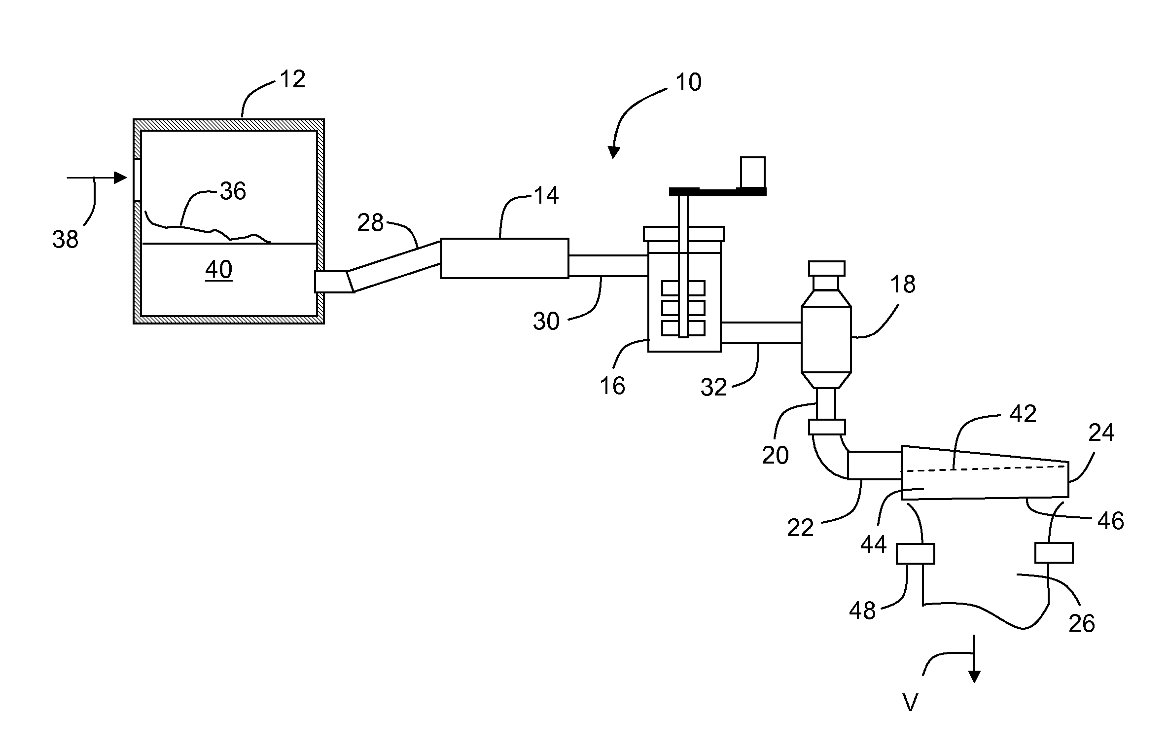
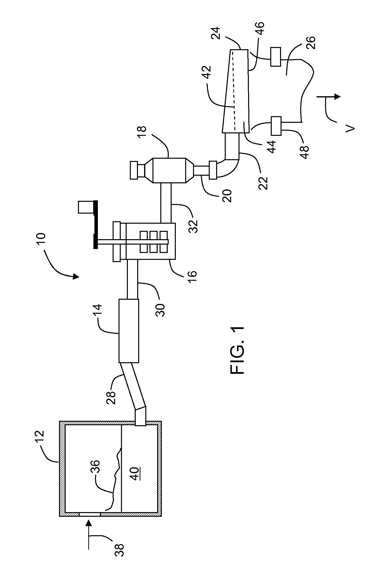
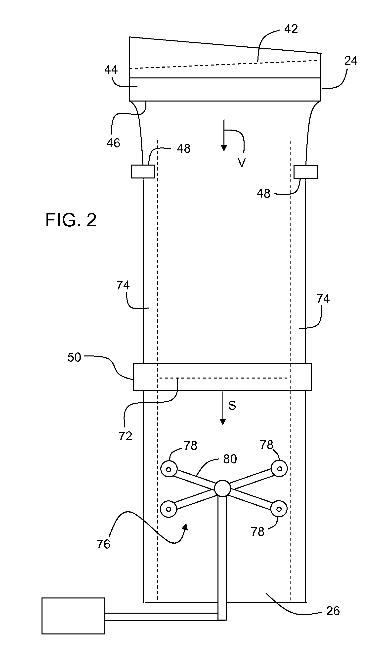
[0022]FIG. 1 illustrates an exemplary embodiment of a fusion glass making system 10 for forming a glass sheet comprising melting furnace 12, fining vessel 14, stirring vessel 16, receiving vessel 18, downcomer 20, inlet 22 and forming body 24 from which a thin, continuously moving ribbon 26 of glass descends. Glass...


PUM

PropertyMeasurementUnit
Timeaaaaaaaaaa
Frequencyaaaaaaaaaa
Frequencyaaaaaaaaaa

Abstract

Disclosed is a method of separating a glass sheet from a moving glass ribbon, wherein the glass ribbon comprises thickened bead portions. The method comprises weakening the bead portions of the ribbon using laser-initiated ablation at the bead portions to overcome the potential for uncontrolled cracking through the bead portion.

Description

BACKGROUND[0001]1. Field[0002]The present invention relates to a method for low energy separation of a glass ribbon, and in particular a method of separating a glass ribbon wherein the glass ribbon comprises non-parallel major surfaces.[0003]2. Technical Background[0004]Glass sheets produced with a down draw process, such as a fusion down draw process or a slot draw process, typically begin by producing from a molten glass material a glass ribbon that descends from a forming body. The glass ribbon is subsequently cut or separated into individual glass sheets at a location where the glass of the ribbon has been sufficiently cooled, and a viscosity reached where the ribbon has entered into an elastic state. More simply stated, the portion of the ribbon where the separation takes place is considered to be a solid. However, as the glass ribbon descends from the forming body the ribbon width has a tendency to attenuate and the edge portions of the ribbon thicken. These thickened edge por...

Claims


Application Information

Patent Timeline
IPC IPC(8): C03B17/06C03B21/00
CPCC03B17/06C03B33/0215B65G2249/04C03B21/00C03B33/082C03B33/091
Inventor ABRAMOV, ANATOLI A.YU, JAE H.ZHOU, NAIYUE
Owner CORNING INC
Learn More