Tibial bearing component for a knee prosthesis with improved articular characteristics

Active Publication Date: 2013-05-23
ZIMMER INC
View PDF0 Cites 38 Cited by
  • Summary
  • Abstract
  • Description
  • Claims
  • Application Information

AI Technical Summary

Problems solved by technology

However, these prior art anterior relief spaces have not been convex across the entire anterior/p

Method used


Image

  • Tibial bearing component for a knee prosthesis with improved articular characteristics
  • Tibial bearing component for a knee prosthesis with improved articular characteristics
  • Tibial bearing component for a knee prosthesis with improved articular characteristics

Examples


Embodiment Construction

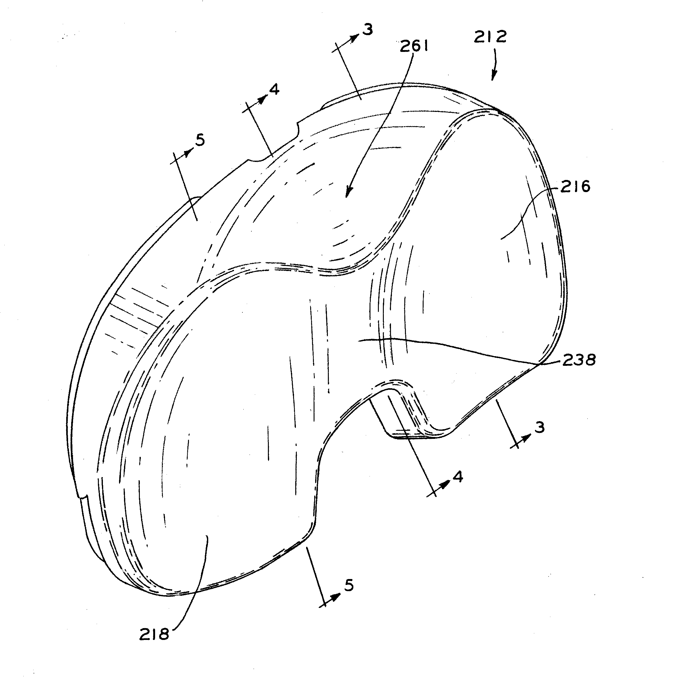
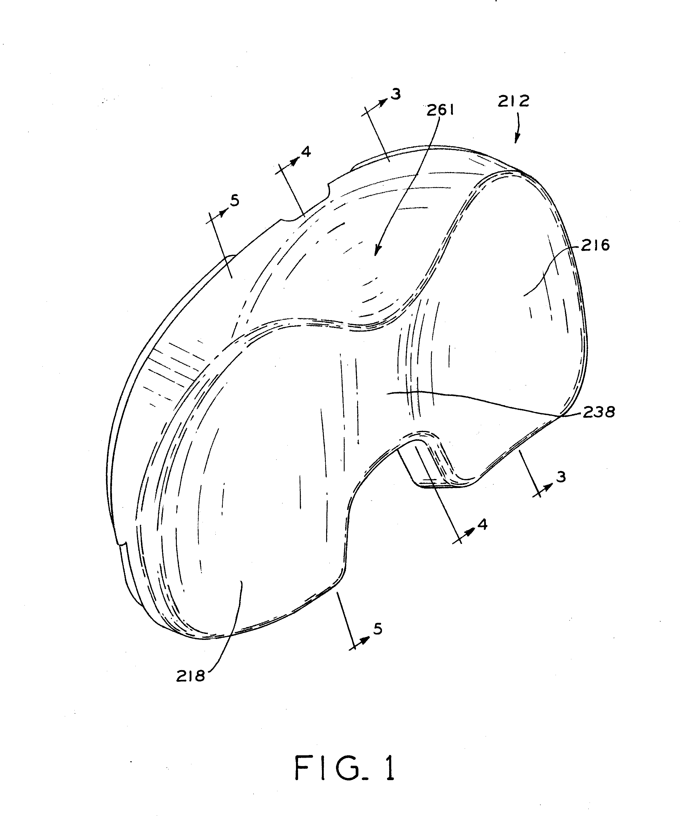
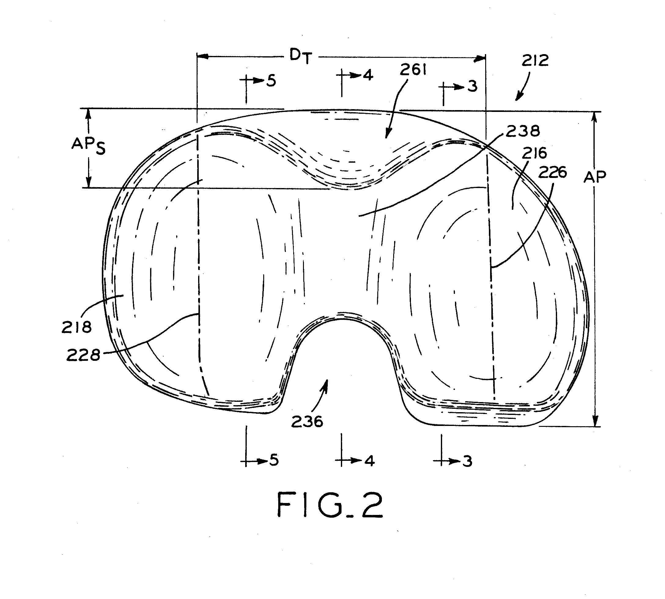
[0026]The present disclosure provides tibial bearing components for a knee prosthesis in which the bearing components have a rounded, sagittally convex anterior relief space which functions to protect soft tissues during knee articulation.

[0027]As used herein, “proximal” refers to a direction generally toward the torso of a patient, and “distal” refers to the opposite direction of proximal, i.e., away from the torso of a patient. “Anterior” refers to a direction generally toward the front of a patient or knee, and “posterior” refers to the opposite direction of anterior, i.e., toward the back of the patient or knee. In the context of a prosthesis alone, such directions generally correspond to the orientation of the prosthesis after implantation, such that a proximal portion of the prosthesis is that portion which will ordinarily be closest to the torso of the patient, the anterior portion closest to the front of the patient's knee, etc.

[0028]Similarly, knee prostheses in accordance ...


PUM


Abstract

An orthopaedic knee prosthesis includes a tibial bearing component with surface features which operate to protect adjacent soft tissues of the natural knee throughout a wide range of flexion. More particularly, the tibial bearing component provides an anterior relief space disposed between the dished lateral and medial articular compartments, in which the relief space is convex as viewed from a sagittal perspective across the medial/lateral extent of the relief space.

Description

BACKGROUND[0001]1. Technical Field[0002]The present disclosure relates to orthopaedic prostheses and, specifically, to articular tibial components in a knee prosthesis.[0003]2. Description of the Related Art[0004]Orthopaedic prostheses are commonly utilized to repair and / or replace damaged bone and tissue in the human body. For a damaged knee, a knee prosthesis may be implanted using a tibial baseplate, a tibial bearing component, and a distal femoral component. The tibial baseplate is affixed to a proximal end of the patient's tibia, which is typically resected to accept the baseplate. The femoral component is implanted on a distal end of the patient's femur, which is also typically resected to accept the femoral component. The tibial bearing component is placed between the tibial baseplate and femoral component, and may be fixed upon or slidably coupled to the tibial baseplate.[0005]The tibial bearing component, which may also be referred to as a tibial insert or meniscal componen...

Claims


Application Information

Patent Timeline
IPC IPC(8): A61F2/38
CPCA61F2/3886A61F2/3868A61F2002/30616A61F2/389A61F2002/30604
Inventor PARISI, RAYMOND C.HABEGGER, ABRAHAM P.WALKER, PETER S.BLAYLOCK, JEFF C.MACKE, KATHLEEN P.
Owner ZIMMER INC
Why Eureka
Try Eureka