
Protective switch with status detection

a technology of status detection and protective switch, which is applied in the direction of relays, protective switch details, instruments, etc., can solve the problems of unintentional switch left, device disablement, and drawbacks persisting

Active Publication Date: 2013-05-16
ABB (SCHWEIZ) AG
View PDF18 Cites 17 Cited by
  • Summary
  • Abstract
  • Description
  • Claims
  • Application Information

AI Technical Summary

Benefits of technology

The present invention provides switch assemblies for selectively opening and closing electrical connections between protective relays and potential or current sensors. The switches have individual blades that move between open and closed positions and a switch position sensor proximate to the blade to detect its position. An indicator optically displays which blades are open based on the sensor's signals. This system allows for the safe and efficient control of electrical connections in a variety of situations.

Problems solved by technology

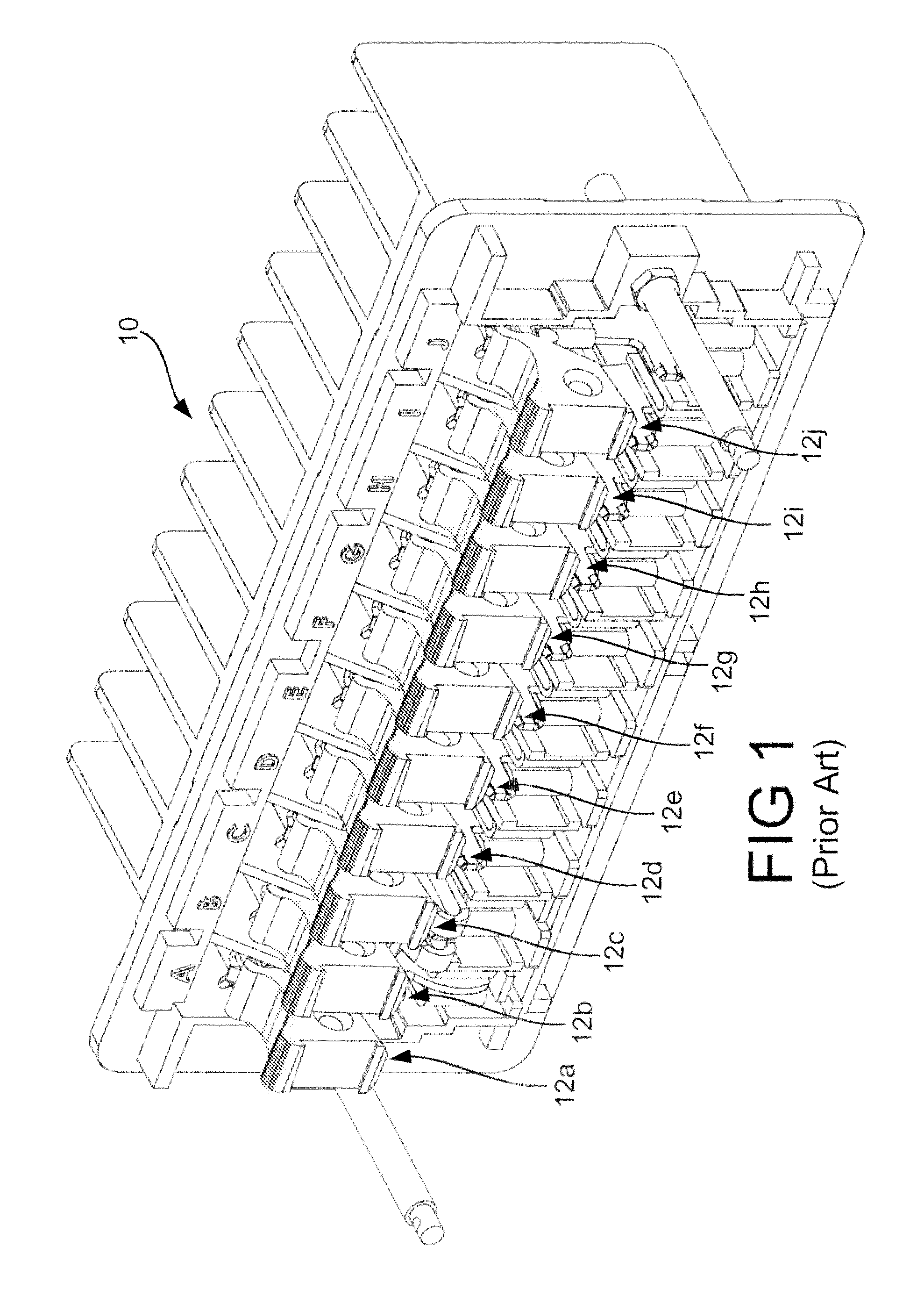
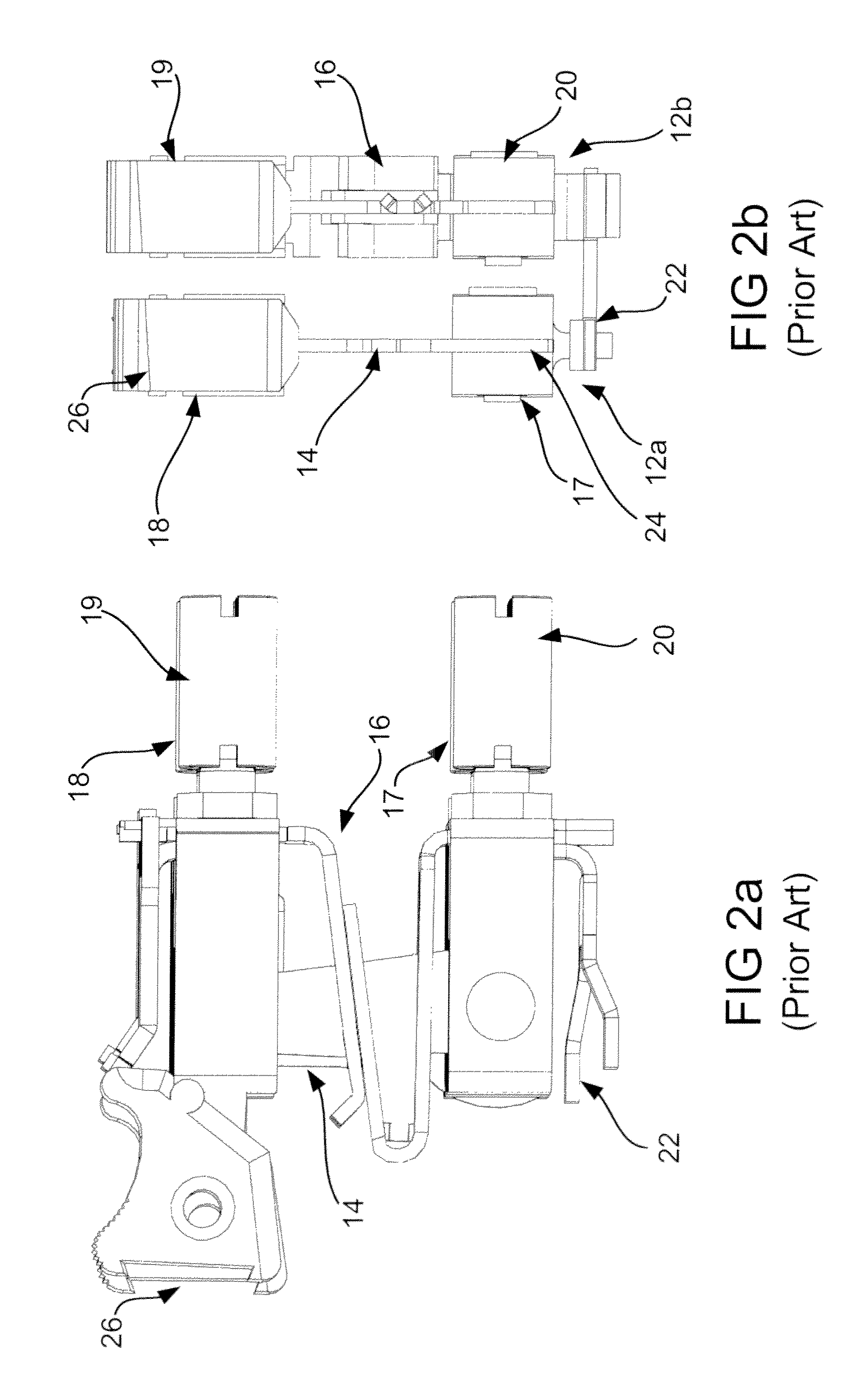
Though prior art test switches have proved remarkably dependable, drawbacks persist.
The power system may be restored and the test switch unintentionally left in a configuration that disables the device.
Such conditions could cause the protection and control equipment to fail.
Other potential issues exist that may affect relay performance, such as blown fuses, changed wires, or changes to the topology of the protection and control scheme (either intentional or unintentional).
Any of these conditions may lead to incorrect operations or failures of the relay.

Method used


Image

  • Protective switch with status detection
  • Protective switch with status detection
  • Protective switch with status detection

Examples


Embodiment Construction

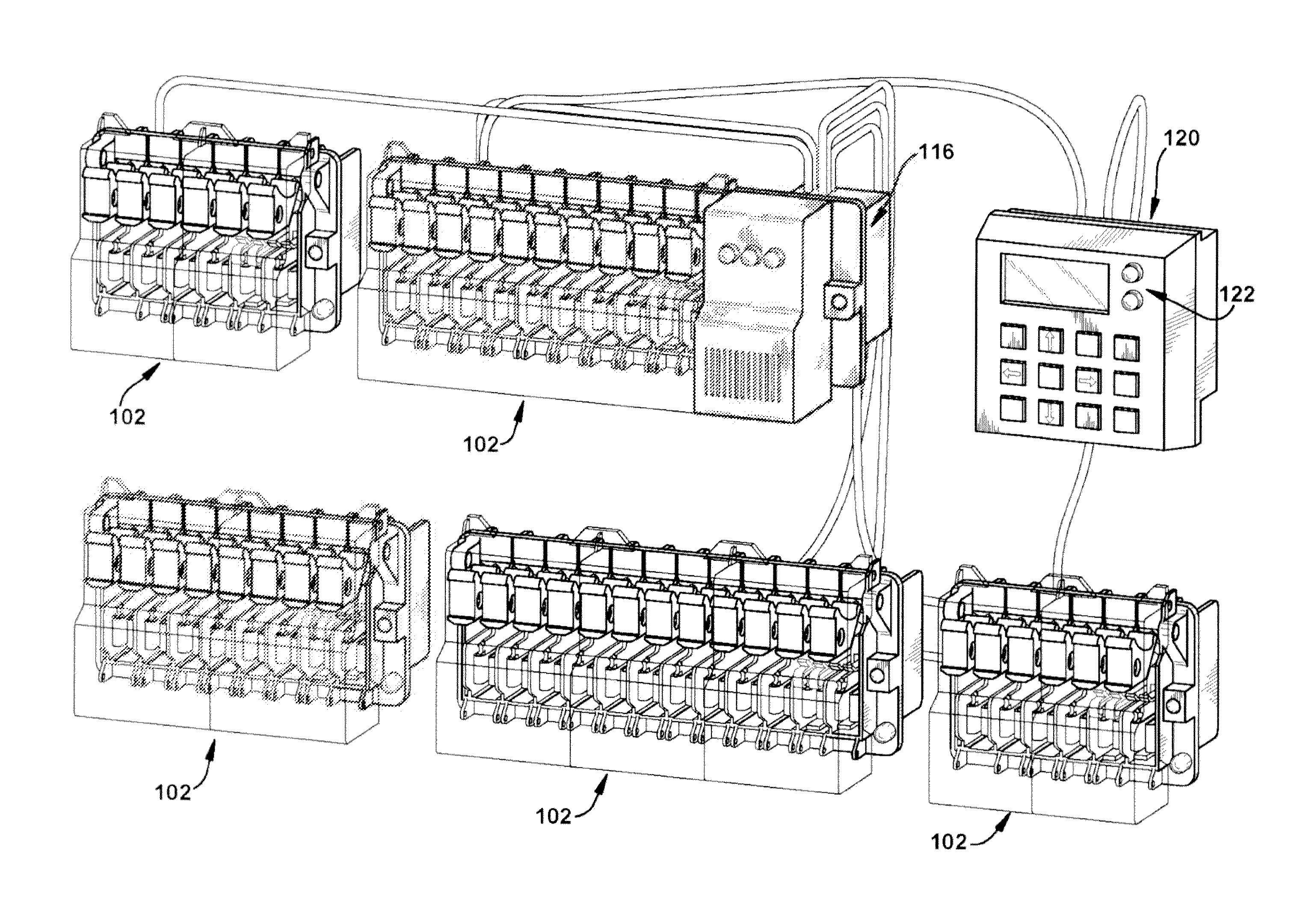
[0032]With reference now to FIG. 3, an exemplary installation 100 is shown, including a plurality of switch assemblies 102. Switch assemblies 102 each include a plurality of individual switches 104 that are modular and horizontally stackable to provide flexibility and efficiency. Each switch assembly 102 includes a plurality of individual switches 104 (see FIG. 4) arranged in a logical grouping and covered by a movable safety cover. For example, one switch assembly 102a may include switches 104 for differential protection for a transformer. A second switch assembly 102b may include switches 104 for the primary protection for a transformer. A third grouping 102c may include switches 104 for backup protection for a transformer. Another logical grouping 102d may include switches 104 for all protection for a given transformer. Any number of groupings may be used, to provide a convenient interface for an operator.

[0033]With reference now to FIG. 4, as discussed above, each switch assembl...


PUM


Abstract

A protective switch assembly (100) includes switch position sensors (109) that sense switch blade (14) position and indicate whether one or more switches (104) are open. According to another aspect, the voltage and current of the switch circuits are monitored to determine switch position as well as overall circuit status.

Description

FIELD OF INVENTION[0001]The present application is directed to protective relay switches, and more particularly to test switches having status detection means.BACKGROUND[0002]Protective relays are commonly used in electric utility applications to detect various possible problems in the electrical power output and thus protect expensive equipment such as motors and generators. Protective relays continuously monitor power systems to assure maximum continuity of electrical service with minimum damage to life and property.[0003]Some of today's protection applications are, without limitation: motor, generator, transformer, station-bus, line and circuit, system ground, network systems, pilot wire, pilot channel, transmission line, pilot relying, backup, reclosing, synchronizing, load-shedding, frequency and many more. Typically, protective relays, meters and instruments receive their input signals from sensors (commonly current transformers and potential transformers) which step down the ...

Claims


Application Information

Patent Timeline
Patent Type & Authority Applications(United States)
IPC IPC(8): H01H71/04
CPCG01R31/3277H01H2071/048H01H83/04H01H71/04H01H21/54
Inventor BALL, ROY
Owner ABB (SCHWEIZ) AG
Learn More