
Direct Manufacture of Orthodontic Aligner Appliance

a manufacturing process and aligner technology, applied in the field of orthodontic appliances, can solve the problems of inconvenient delivery of appliances, inconvenient treatment, and inconvenient treatment of patients, and achieve the effect of rapid delivery of appliances

Inactive Publication Date: 2013-04-18
ORMCO CORP
View PDF6 Cites 268 Cited by
  • Summary
  • Abstract
  • Description
  • Claims
  • Application Information

AI Technical Summary

Benefits of technology

The patent allows for the appliance to be made in a different location than where the digital model was created, such as the orthodontic practitioner's office or the patient's home. This allows for faster delivery of the appliance to the patient and practitioner.

Problems solved by technology

Patients undergoing orthodontic treatment using metal orthodontic brackets, however, may be embarrassed by the visibility of metal, which is not cosmetically pleasing.
Typically, a series of aligners is required to fully treat the patient because the degree of movement produced by an aligner is limited.
As can be seen, the fabrication of aligners is a tedious process which compounds both cost and time of treatment for the patient.
Since such an orthodontic treatment may require, for example, 25 intermediate reset molds to represent 25 stages of treatment progress, the cost and time required for the necessary steps of mold making, aligner formation, and trimming, may be prohibitively high.
The cost is additive, as each new stage in treatment or each change in treatment requires the production of a new mold.
Likewise, the cost of storing a series of molds for each patient throughout treatment may be formidable.
Treatment of malocclusion by aligners faces challenges other than the difficulty of manufacture.
Specifically, aligners fastened with attachments may prove very difficult to install, as a result of the limited number of shapes that the attachment apertures on the aligner may take consistently with the Invisalign® manufacturing process; specifically, the attachment apertures must be formed by thermoforming over a stereolithographically-generated positive tooth model, which limits the type of apertures that may be made.
Moreover, aligners may bind with the attachments and prove very difficult to remove.
This opens the patient's bite and typically intrudes the rear molars as a consequence of the unbalanced occlusion force on the rear molars.
One result of this can be TMJ injury after the removal of the aligner because the force of the mandible is no longer resisted by the rear molars in the absence of the aligners.
For many patients aligners fabricated manually or by thermoforming on a positive model are uncomfortable and can irritate the patient's gingiva and / or tongue to such an extent that the soft tissue becomes inflamed and can potentially bleed.
This discomfort is generally caused because the aligner is trimmed inaccurately to the patient's gingival margin.
The inaccuracy in trimming is generally caused by the minimum size of the trimming tool particularly on the anterior lingual side where the aligner interferes with the tongue.
In addition, the location where the aligner is trimmed can cause a sharp flange to be created at the base of the aligner near the gingival margin particularly on the lingual side.

Method used

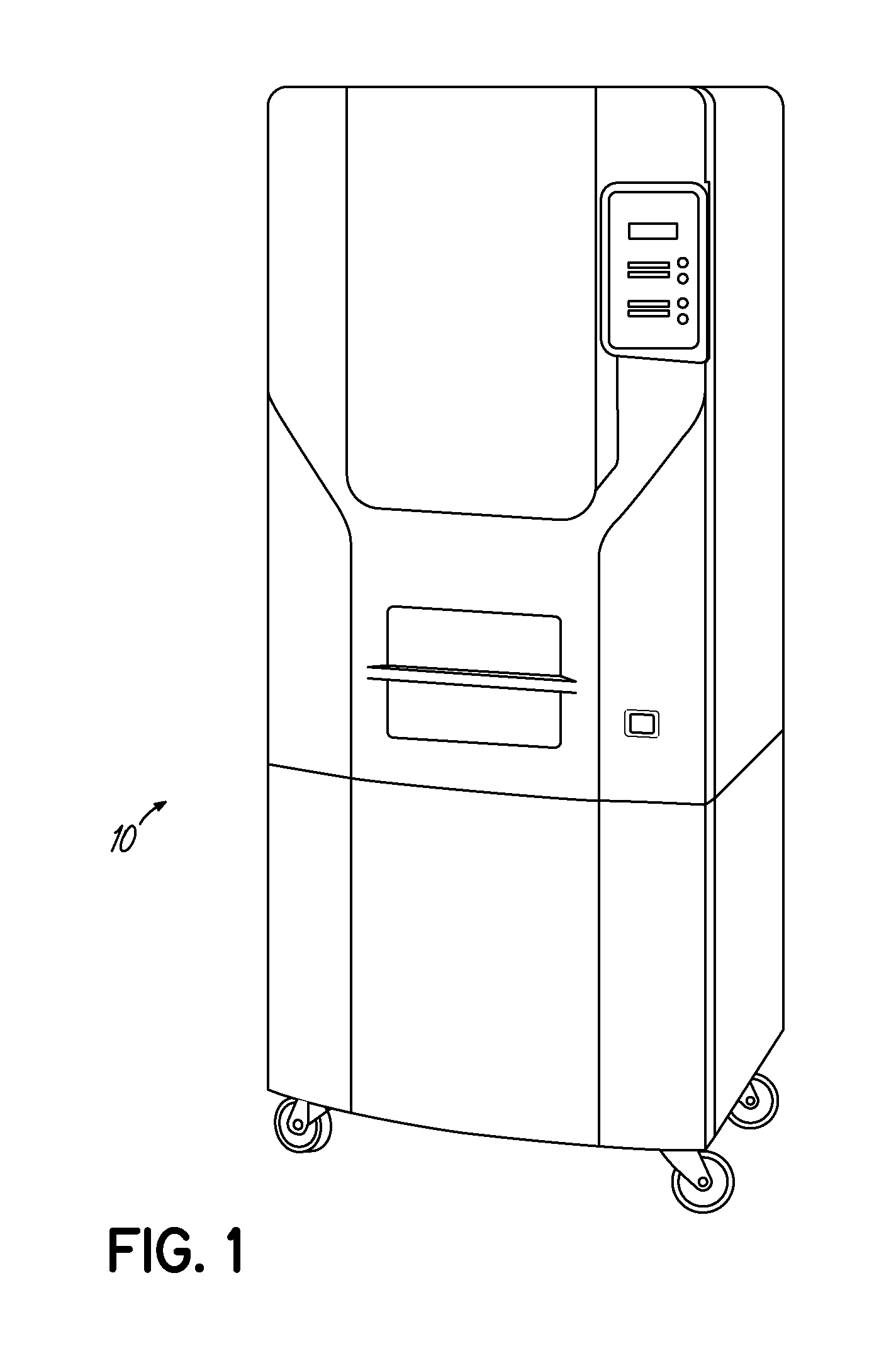
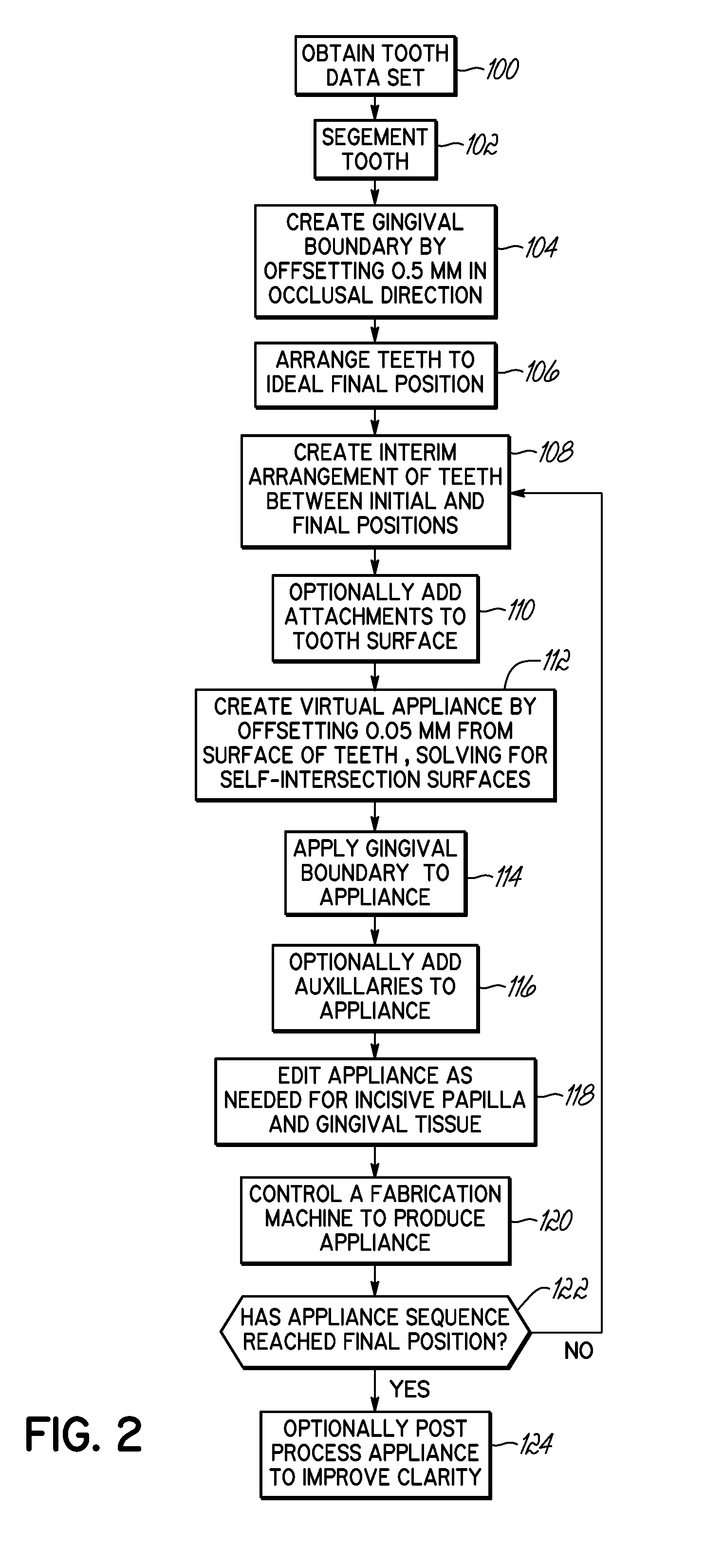

Image

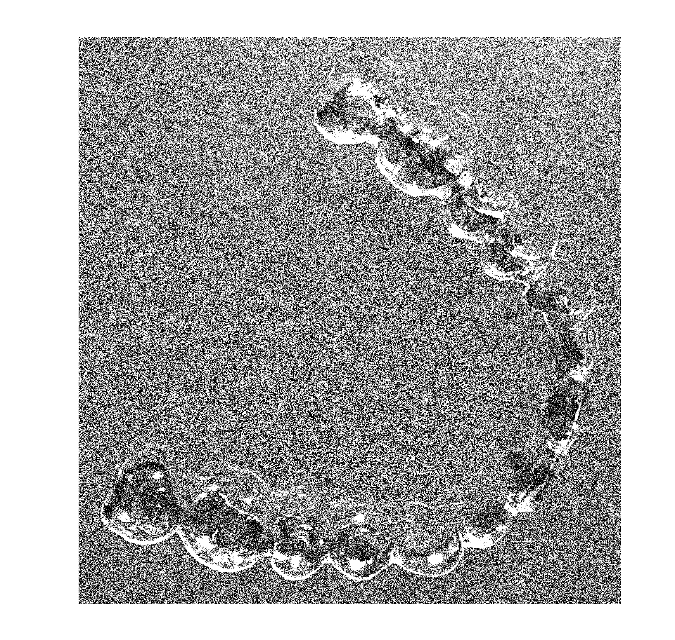
  • Direct Manufacture of Orthodontic Aligner Appliance
  • Direct Manufacture of Orthodontic Aligner Appliance
  • Direct Manufacture of Orthodontic Aligner Appliance

Examples


Embodiment Construction

[0035]In general, one embodiment of the invention includes a directly manufactured orthodontic appliance capable of moving teeth according to a predetermined treatment plan, such as illustrated in FIGS. 3 and 4. In particular, the orthodontic appliance may move one or more teeth from one orientation to another which advances the overall orientation of the teeth toward their final orthodontically correct and aesthetically desired positions. In one embodiment of the invention, a series of individual orthodontic appliances may be utilized for complete orthodontic treatment. Accordingly, each appliance in the series may move one or more teeth a prescribed amount. Cumulatively, these individual amounts may result in complete treatment of the patient's malocclusion.

[0036]By way of example only, in one embodiment, the orthodontic appliance may include an aligner. Such aligners may be similar to those used in the prior art, but differ in the manner in which the aligner is made, and in detai...


PUM


Abstract

A method for direct fabrication of an orthodontic device having tooth-fitting cavities, such as an aligner, using layer-by-layer printing of a single or multiple polymeric materials. The cavities of the appliance are defined by the boundaries of the multiple layers, encapsulating up to fourteen teeth of a patient, and shaped to apply a load to at least one tooth that is sufficient to cause movement of the tooth, and remodeling of the adjacent bone. A series of such appliances may be used to treat malocclusion of teeth, each directly manufactured appliance used in series to incrementally move one or more teeth from initial positions toward a desired final position. The appliance may be fabricated with a variety of disclosed materials, and may include auxiliary features for interaction with other orthodontic elements.

Description

RELATED APPLICATION[0001]The Present application claims priority to U.S. Ser. No. 61 / 546,554 filed Oct. 12, 2011, the disclosure of which is hereby incorporated herein by reference in its entirety.FIELD OF THE INVENTION[0002]The present invention is directed to an orthodontic appliance and particularly to orthodontic aligners.BACKGROUND OF THE INVENTION[0003]In conventional orthodontic treatment, an orthodontist or an assistant affixes an orthodontic appliance, such as orthodontic brackets, to the patient's teeth and engages an archwire into a slot of each bracket. The archwire applies corrective forces that coerce the teeth to move into orthodontically correct positions. Traditional ligatures, such as small elastomeric O-rings or fine metal wires, are employed to retain the archwire within each bracket slot. Due to difficulties encountered in applying an individual ligature to each bracket, self-ligating orthodontic brackets have been developed that eliminate the need for ligatures...

Claims


Application Information

Patent Timeline
Patent Type & Authority Applications(United States)
IPC IPC(8): A61C7/08A61F5/56
CPCA61C7/36A61C7/08A61C7/002A61C13/0013B33Y80/00
Inventor ANDREIKO, CRAIG A.KITCHING, IAN
Owner ORMCO CORP
Learn More