
Drilling Mud Agitator With Shaft Retainer

a technology of agitator and shaft, which is applied in the direction of mixing, chemistry apparatus and processes, mixers, etc., can solve the problems of time-consuming, system maintenance, and putting the workman in danger, and achieve the effect of quick and easy removal

Inactive Publication Date: 2013-04-11
PROCESS SOLUTIONS INT
View PDF11 Cites 10 Cited by
  • Summary
  • Abstract
  • Description
  • Claims
  • Application Information

AI Technical Summary

Benefits of technology

The patent describes a mechanism for securely attaching an agitator shaft to a motor. This mechanism allows for easy removal of the coupling halves and the motor for repair or replacement. The technical effect is an improved design for attaching agitators to motors that makes maintenance easier and more efficient.

Problems solved by technology

A difficulty arises when maintenance must be performed on the system within the mud tank or repair or replacement of the agitator motor.
This is not only time consuming, it places the workman in danger.

Method used


Image

  • Drilling Mud Agitator With Shaft Retainer
  • Drilling Mud Agitator With Shaft Retainer
  • Drilling Mud Agitator With Shaft Retainer

Examples


Embodiment Construction

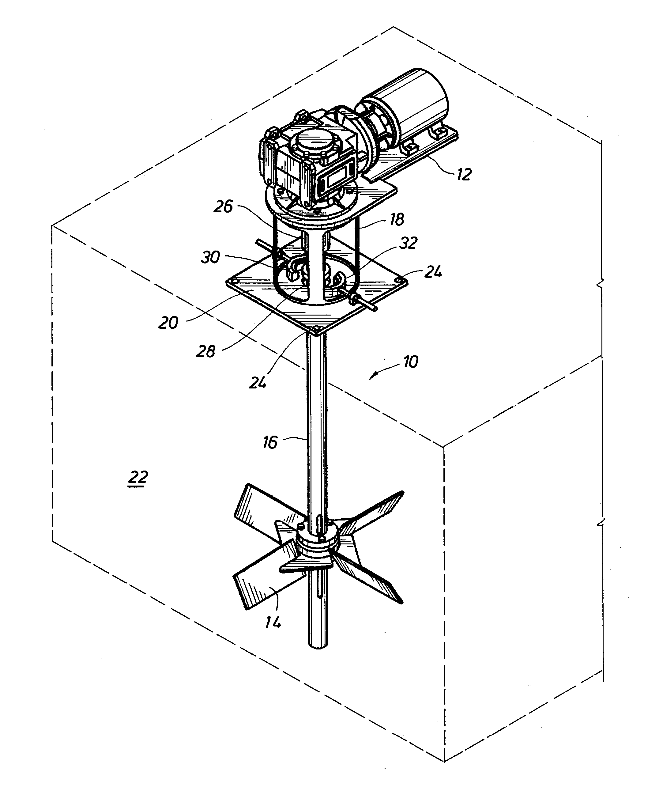
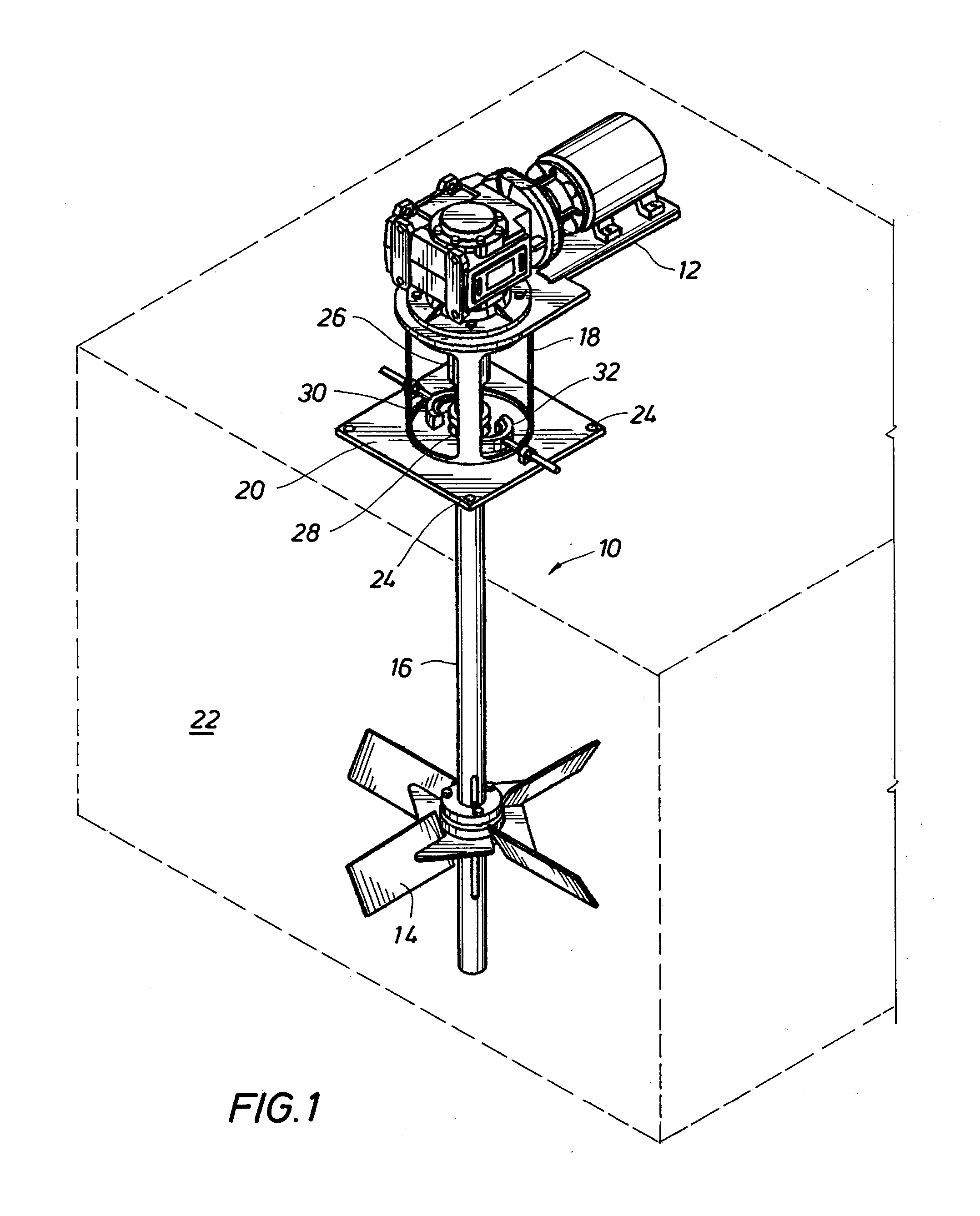
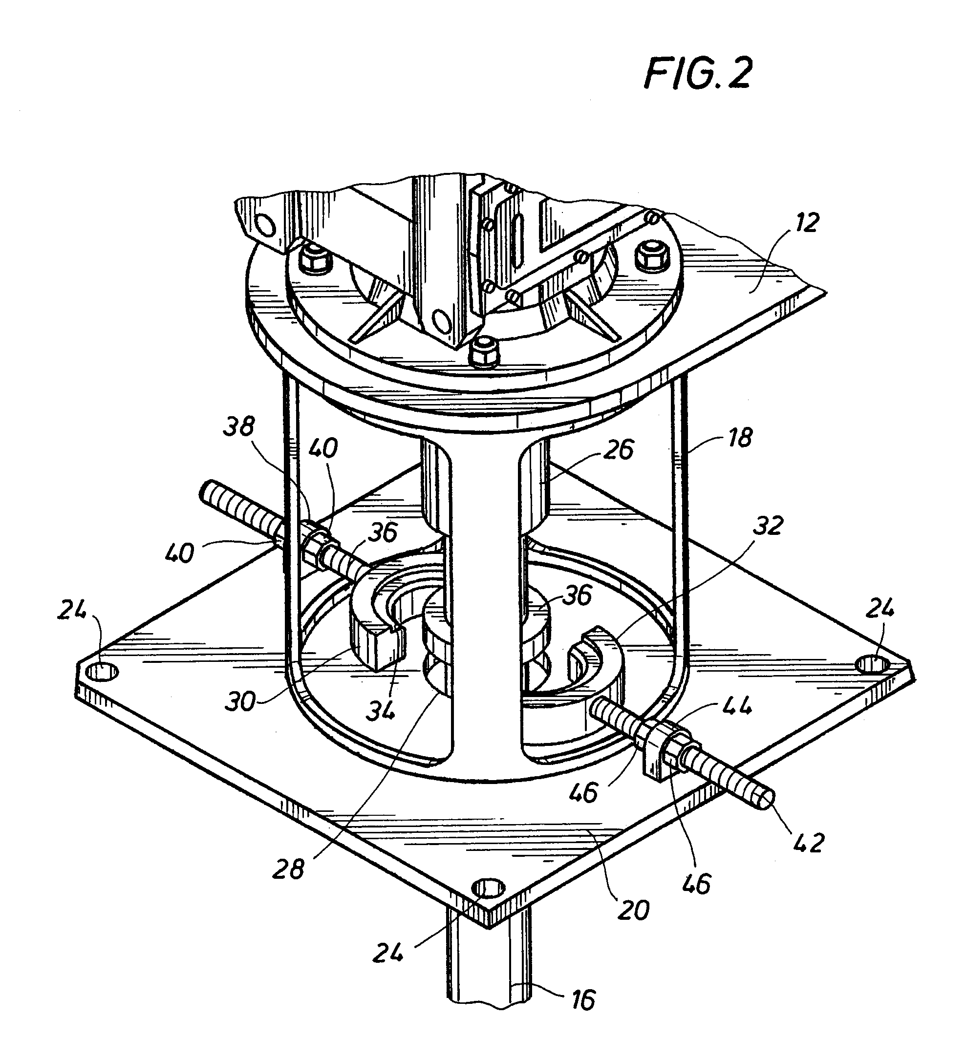
[0016]FIGS. 1, 2, and 3 depict an agitator system 10 in accordance with the teachings of the present invention. The system primarily comprises a gearbox / motor assembly 12, an impeller 14, both coupled together with an agitator shaft 16. The gearbox / motor assembly 12 is mounted on an open work pedestal 18 which is affixed to a cover plate 20. The cover plate is secured to the top of a mud tank 22, which is shown in FIG. 1 as having flat rectangular sides for illustration purposes only. Preferably, the mud tank 22 is a cylindrical tank with a round bottom so that the tank does not present any dead zones for the free flow of agitated mud within the tank. The cover plate 20 is preferably removably mounted to the top of the tank 22 with a set of screws 24, for example.

[0017]The gearbox / motor assembly 12 is preferably secured to the agitator shaft 16 with a shaft coupling 26, shown more clearly in FIGS. 2 and 3. The agitator shaft 16 extends through a hole 28 in the cover plate 20. Thus, ...


PUM


Abstract

A mechanism secures a mud agitator motor on top of a man-way cover on a mud tank. The mechanism includes a retractable shaft retainer element arranged to engage a retainer block affixed to the agitator shaft. A pair of hemi-cylindrical coupling halves couple the agitator motor shaft to the agitator shaft. The retractable shaft retainer element, once engaged with the retainer block, secures the agitator shaft. The coupling halves can then be quickly and easily removed, and the motor can then be removed for repair or replacement.

Description

FIELD OF THE INVENTION[0001]The present invention relates generally to the field of drilling mud systems and, more particularly, to a drilling mud agitator assembly including a shaft retainer that permits disassembly of the agitator shaft from outside the agitator tank.BACKGROUND OF THE INVENTION[0002]The present invention relates to a device for agitating drilling mud having particulate solids entrained therein, such as for example drill cuttings and various drilling mud additives. In operation, such a device is typically mounted atop a mud tank in which one or a plurality of agitating devices may extend.[0003]As described in U.S. Pat. No. 4,516,860 to van der Laan et al., drilling mud is commonly used in oil and gas drilling operations to cool and lubricate the drill bit and flush drill cuttings from the bore hole back up to the surface. Drilling mud must have an adequately high specific weight so that the column of drilling mud controls the liquids and / or gases in the formation o...

Claims


Application Information

Patent Timeline
Patent Type & Authority Applications(United States)
IPC IPC(8): B01F7/22B01F27/91
CPCB01F7/22B01F7/1695B01F7/00725B01F27/213B01F27/88B01F27/91
Inventor GOUIN, LOUIS CHARLES
Owner PROCESS SOLUTIONS INT
Learn More