Motor housing thermal sensing

a technology for thermal sensing and motor housings, applied in the direction of heat measurement, positive displacement liquid engines, instruments, etc., can solve problems such as housing overheating

Active Publication Date: 2013-04-04
HAMILTON SUNDSTRAND CORP
View PDF11 Cites 11 Cited by
  • Summary
  • Abstract
  • Description
  • Claims
  • Application Information

AI Technical Summary

Benefits of technology

[0009]FIG. 3 is a cut-away front perspective view of the motor driven compressor apparatus of FIG. 1; and

Problems solved by technology

The motor driven compressors are typically mounted to a fuselage fairing, which is considered a flammable leakage zone as it can potentially release fuel vapors.
Bearing (air or thrust) failures in the motor driven compressors can cause the housing to overheat to temperatures that are of concern in aircraft fuel vapor zones.

Method used


Image

  • Motor housing thermal sensing
  • Motor housing thermal sensing
  • Motor housing thermal sensing

Examples


Embodiment Construction

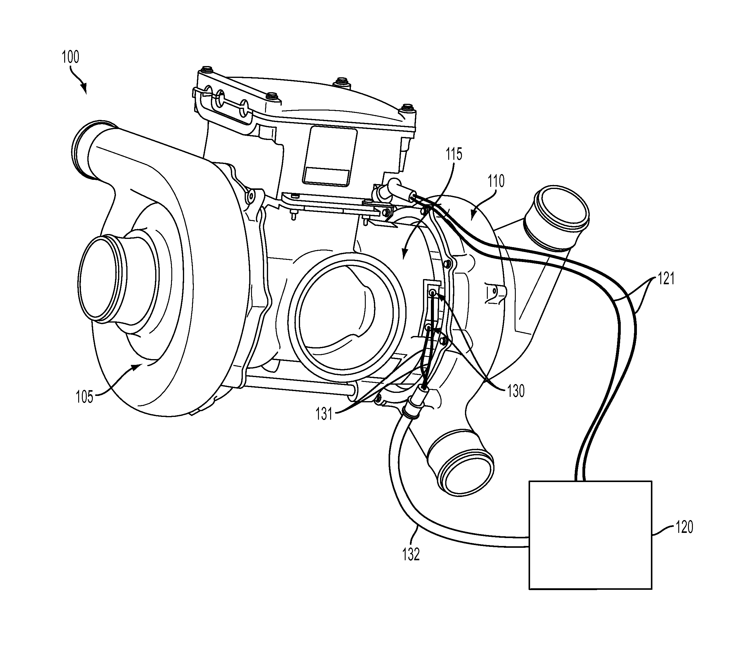
[0011]FIG. 1 illustrates a motor driven compressor apparatus 100 in which excessive internal heat can be detected externally, in accordance with one embodiment. Several details of the system have been eliminated for illustrative purposes. It will be appreciated that the motor driven compressor apparatus 100 is an illustrative example. Many other types of motor and generators that include internal bearings or components that can fail and generate heat that can be detected externally are contemplated in other embodiments. The apparatus 100 illustrated in FIG. 1 is a motor driven system having a two-stage compressor. As such, the apparatus 100 includes a first compressor stage 105 and a second compressor stage 110. In one embodiment, the first and second compressor stages 105, 110 are centrifugal compressors which utilize low solidity diffusers to maximize operating range. The apparatus 100 further includes an electric motor 115. In one embodiment, the electric motor 115 includes a thr...


PUM

PropertyMeasurementUnit
temperatureaaaaaaaaaa
internal temperaturesaaaaaaaaaa

Abstract

A motor driven compressor apparatus includes a first stage compressor, a second stage compressor, an electric motor disposed between and coupled to the first stage compressor and the second stage compressor, thermal sensors disposed on the electric motor and configured to externally measure internal temperatures of the electric motor or internal bearings or components, and an external controller coupled to the electric motor and to the thermal sensors, and configured to at least one of slow down a speed of the electric motor and shut down the electric motor in response to at least one of an excess of a predetermined internal temperature and a rate of internal temperature change.

Description

BACKGROUND OF THE INVENTION[0001]The present invention relates to motors and generators, and more specifically, to thermal sensors for motors and generators to externally detect internal heat.[0002]Motor driven compressors, typically used on aircraft, produce pressurized air which is routed to air separation modules in nitrogen generation systems for nitrogen enrichment. The nitrogen-enriched air is then distributed into the main and center fuel tanks to maintain a required inerting level. The motor driven compressors are typically mounted to a fuselage fairing, which is considered a flammable leakage zone as it can potentially release fuel vapors. Bearing (air or thrust) failures in the motor driven compressors can cause the housing to overheat to temperatures that are of concern in aircraft fuel vapor zones. As such, it is desirable to monitor the motor driven compressors for overheating.BRIEF DESCRIPTION OF THE INVENTION[0003]Exemplary embodiments include a motor driven compresso...

Claims


Application Information

Patent Timeline
Patent Type & Authority Applications(United States)
IPC IPC(8): F04B49/06H02K11/00G01K13/00
CPCF04D17/12F04D25/0606G01K2205/00G01K13/00F04D27/001
Inventor BEERS, CRAIG M.PALIULIS, JOHN H.
Owner HAMILTON SUNDSTRAND CORP
Why Eureka
Try Eureka