
Methods and instrumentation for orthopedic surgery

a technology for orthopedic surgery and templates, applied in the field of templates, instruments, methods, etc., can solve the problems of manual shaping of standard rigid surgical plates, inability to determine which implants are appropriate, and the rigid trial size template cannot conform to the patient's anatomy

Inactive Publication Date: 2013-03-07
NUVASIVE
View PDF2 Cites 31 Cited by
  • Summary
  • Abstract
  • Description
  • Claims
  • Application Information

AI Technical Summary

Benefits of technology

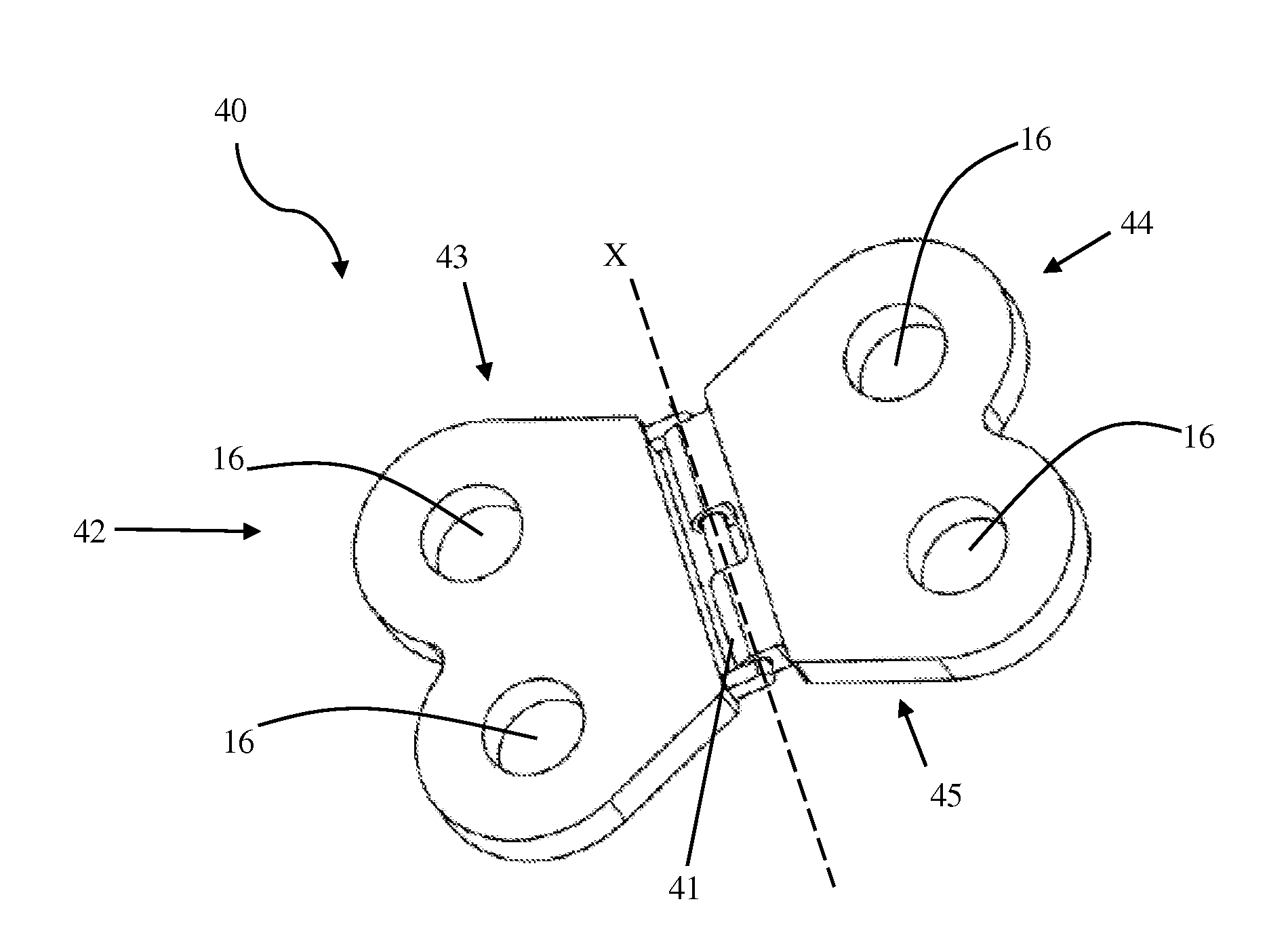
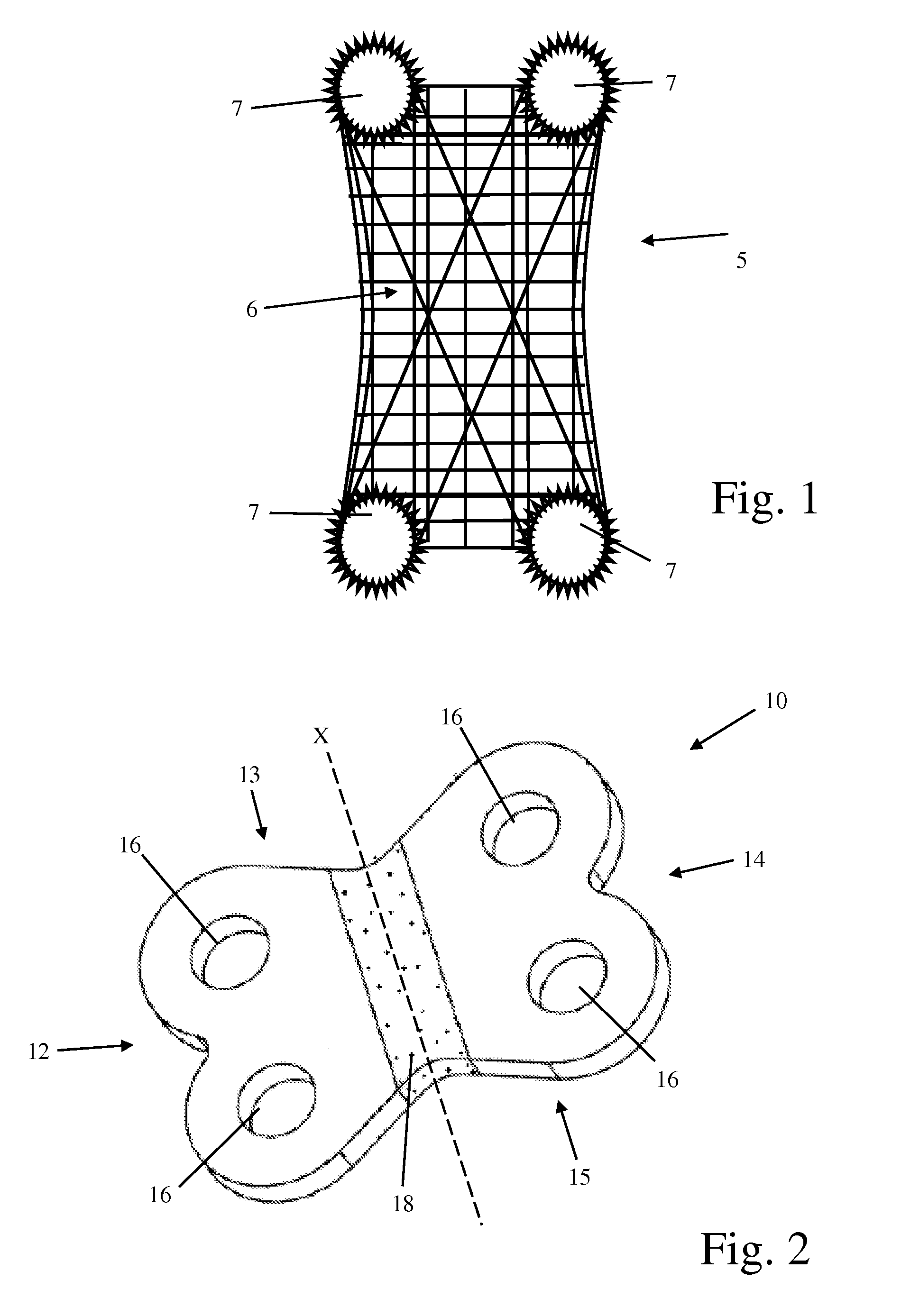
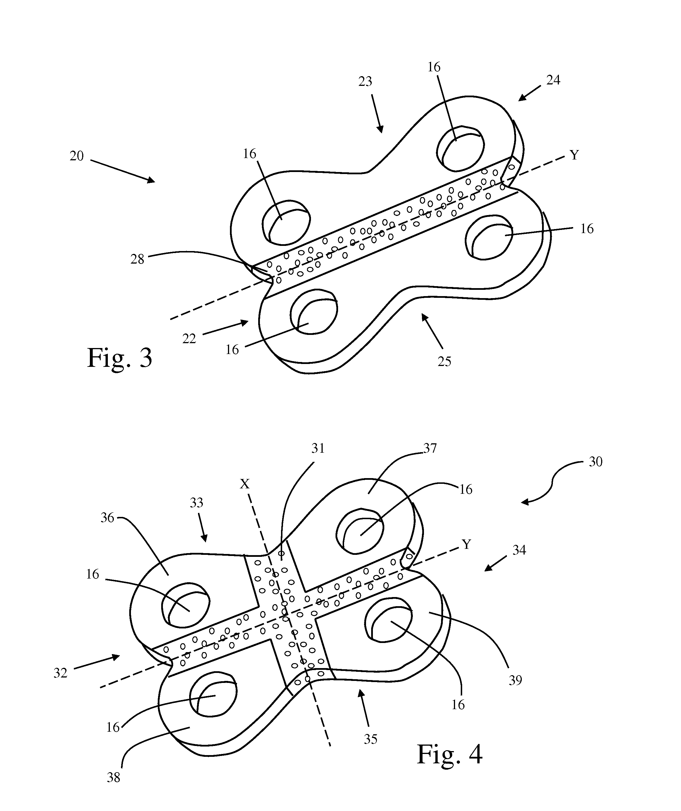
This patent is about a flexible template for a textile-based orthopedic implant that can be easily inserted into the body and positioned correctly for bone screws or other attachment means. The template has lateral ends with apertures that correspond to those on the implant. The template can bend in any direction and is composed of a translucent material to improve visibility during surgery. An inserter instrument is provided in different template end sizes, with an extension that can be adjusted to fit through surgical corridors. The template end has cylindrical extensions around the screw apertures that hold the implant in place during insertion. This invention simplifies the placement of orthopedic implants and improves their accuracy.

Problems solved by technology

Furthermore, in instances where the plate must conform to a bone, such as to protect a fracture or to support fused vertebrae, it can be challenging to manually shape the standard rigid surgical plate to custom fit the desired area.
Because the textile implants are flexible, a typical rigid trial size template mimicking the size and shape of the textile-based implant may not be appropriate to determine which implant is appropriate.
A rigid trial size template cannot conform to the patient's anatomy as a flexible implant can.
It may also be difficult to pass a rigid trial size template through the operative corridor to the target site, where a flexible textile implant would easily pass if folded or bent.

Method used


Image

  • Methods and instrumentation for orthopedic surgery
  • Methods and instrumentation for orthopedic surgery
  • Methods and instrumentation for orthopedic surgery

Examples


Embodiment Construction

[0038]Illustrative embodiments of the invention are described below for the purposes of understanding the principles of the invention. No limitation of the scope of the invention is therefore intended. In the interest of clarity, not all features of an actual implementation are described in this specification. It will be appreciated that in the development of any such actual embodiment, numerous implementation-specific decisions must be made to achieve the developers' specific goals, such as compliance with system-related and business-related constraints, which will vary from one implementation to another. Moreover, it will be appreciated that such a development effort might be complex and time-consuming, but would nevertheless be a routine undertaking for those of ordinary skill in the art having the benefit of this disclosure. The invention disclosed herein boasts a variety of inventive features and components that warrant patent protection, both individually and in combination.

[0...


PUM


Abstract

Surgical instruments and methods aimed at the proper placement and installation of textile-based orthopedic implants. More specifically, the surgical instruments include a flexible template, insertion instrument and multi-pronged awl. The flexible template may be formed of a combination of rigid and flexible materials and is deformable to match the contour of the target anatomy for subsequent placement of a textile-based orthopedic implant. The insertion instrument has a handle and a template end used for holding the flexible template and textile-based implant. The template end has one or apertures with hollow cylindrical extensions for holding the flexible template or textile-based implant and one or more cutout regions for better visualization and affixation of fixation screws. An awl is also provided with one or more prongs to initiate channels for the fixation screws. A method of implanting a textile-based orthopedic implant is also disclosed.

Description

CROSS-REFERENCES TO RELATED APPLICATIONS[0001]The present application is a non-provisional application claiming the benefit of priority under 35 U.S.C. §119(e) to U.S. Provisional Application No. 61 / 219,745, filed Jun. 23, 2009, and entitled “ Methods and Instrumentation for Orthopedic Surgery,” the complete disclosure of which is hereby incorporated by reference in its entirety as if set forth fully herein.BACKGROUND OF THE INVENTION[0002]I. Field of the Invention[0003]The present invention relates to templates, instruments, and methods generally aimed at surgery and, more particularly, to templates, instruments, and methods aimed at the efficient and accurate installation of flexible implants.[0004]II. Discussion of the Prior Art[0005]Rigid plate implants have been used for many years to support bone fractures, reconstruct orthopedic structure across damaged ligaments, and to provide stability between fused spinal vertebrae. Rigid plate implants are usually affixed via fixation el...

Claims


Application Information

Patent Timeline
Patent Type & Authority Applications(United States)
IPC IPC(8): A61B17/88A61B17/56A61B17/80
CPCA61B17/1604A61B17/808A61B17/80A61F2/4684
Inventor RODGERS, W. BLAKESHOSHTAEV, EUGENEEISERMANN, LUKASRIINA, JOSEPHDRYER, RANDALLYOUSSEF, JIMHARDY, MARY CATHERINE
Owner NUVASIVE
Learn More