Antenna device and portable wireless terminal equipped with the same
- Summary
- Abstract
- Description
- Claims
- Application Information
AI Technical Summary
Benefits of technology
Problems solved by technology
Method used
Image

Examples
embodiment 1
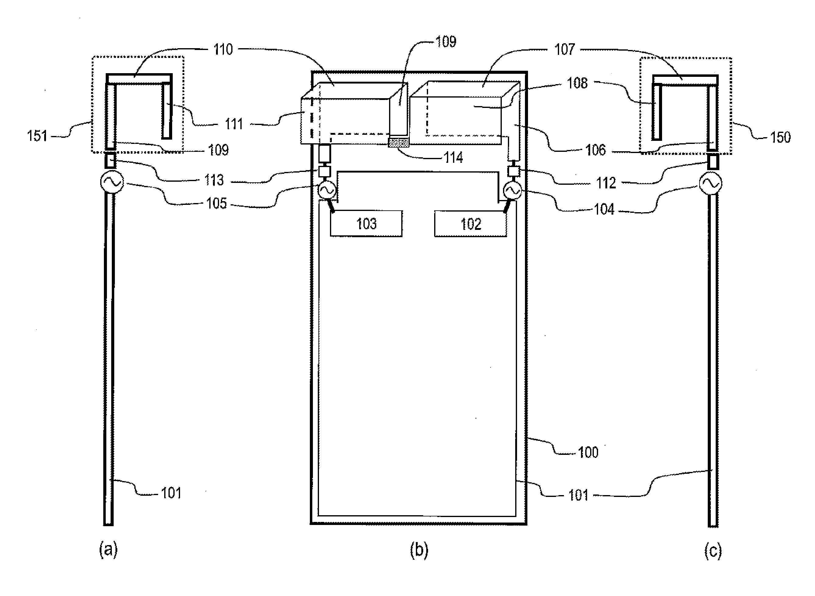
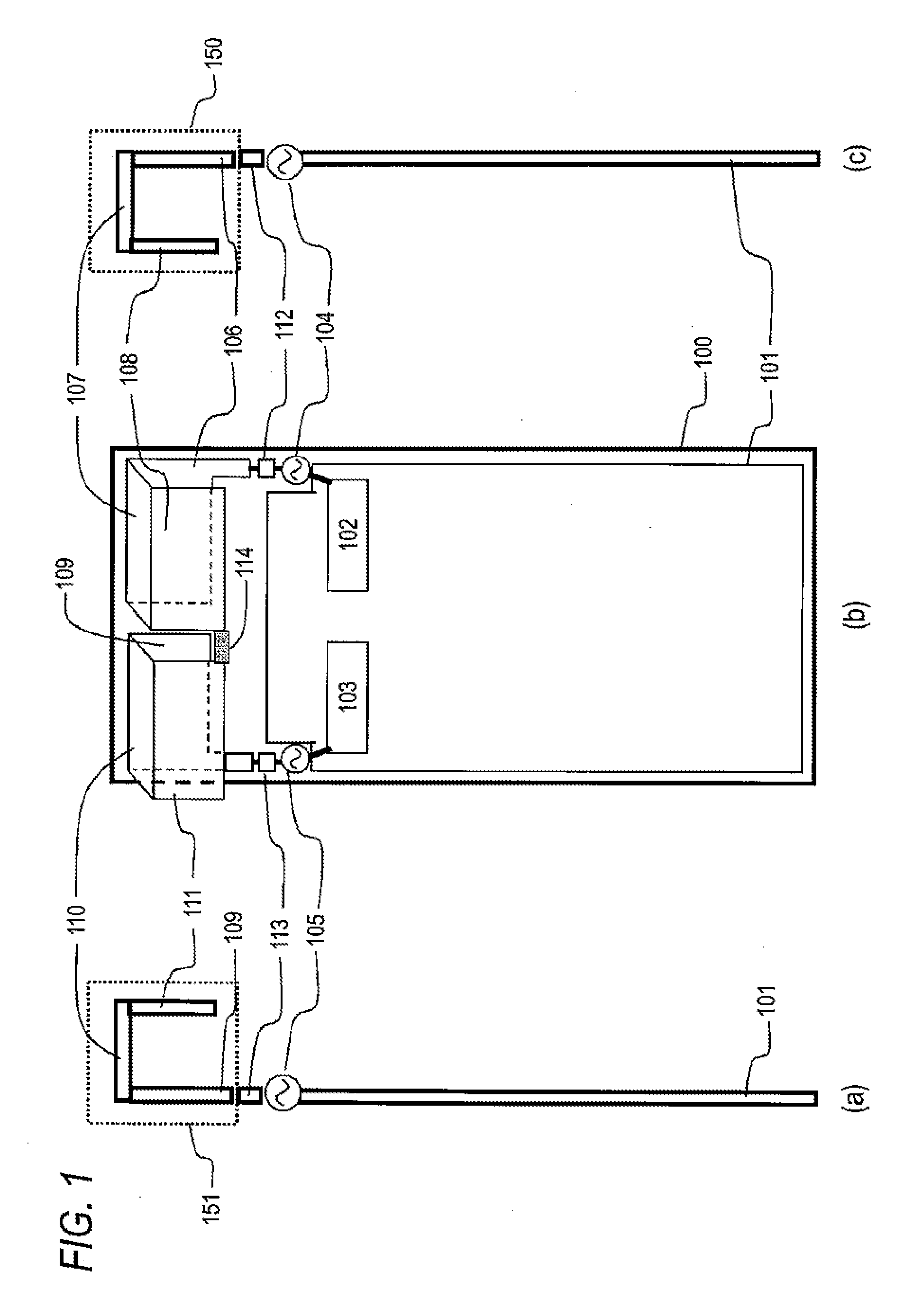
[0034]FIGS. 1(a) to 1(c) are configuration diagrams of a portable wireless terminal according to Embodiment 1 of the present invention. FIG. 1(a) is a configuration diagram of the portable terminal viewed from the left side, and FIG. 1(b) is a diagram showing a view from the front. Further, FIG. 1(c) is a configuration diagram showing a view from the right side.
[0035]As shown in FIGS. 1(a) to 1(c), a circuit board 101 disposed in the portable wireless terminal 100 includes a first wireless circuit section 102. Thus, a first antenna element 150 made of a conductive metal is supplied with a high-frequency signal through a first power supply section 104. Here, the first antenna element 150 includes: a first conductor plate 106 which is conductive and substantially rectangular; a second conductor plate 107 which shares one side of the first conductor plate 106 in a widthwise direction thereof, is disposed thereon at approximately 90 degrees, and is substantially rectangular; and a third...
embodiment 2
[0056]FIG. 7 is a configuration diagram of a portable wireless terminal according to Embodiment 2 of the present invention.
[0057]In FIG. 7, the components common to FIGS. 1(a) to 1(c) will be referenced by the same reference numerals and signs, and description thereof will be omitted.
[0058]In the portable wireless terminal shown in FIG. 7, the connection position of the first connection circuit 114, which interconnects the first antenna element 150 and the second antenna element 151, can be moved to any of a first connection position 201, a second connection position 202, and a third connection position 203. With such a configuration, a degree of freedom in design is improved. Further, for example as shown in FIG. 7, the second connection circuit 115 is disposed at the second connection position 202, whereby it is possible to further minutely adjust the impedance of the mutual coupling between the antenna elements. Thus, the effect that reduces coupling degradation further increases...
embodiment 3
[0059]FIG. 8 is a configuration diagram of a portable wireless terminal according to Embodiment 3 of the present invention.
[0060]In FIG. 8, the components common to FIGS. 1(a) to 1(c) will be referenced by the same reference numerals and signs, and description thereof will be omitted.
[0061]The portable wireless terminal shown in FIG. 8 includes a circuit board pattern 300 that interconnects the position of the first antenna element 150 close to the first impedance matching circuit 112 and the position of the second antenna element 151 close to the second impedance matching circuit 113. With such a configuration, by adjusting the length and the width of the pattern, it is possible to adjust the impedance of the mutual coupling between the antenna elements without using the circuit constants. As a result, it is possible to obtain the effect that reduces coupling degradation.
[0062]Although the present invention has been described in detail with reference to specific embodiments, it wil...
PUM
 Abstract
Description
Claims
Application Information
 - R&D
- Intellectual Property
- Life Sciences
- Materials
- Tech Scout
- Unparalleled Data Quality
- Higher Quality Content
- 60% Fewer Hallucinations
Browse by: Latest US Patents, China's latest patents, Technical Efficacy Thesaurus, Application Domain, Technology Topic, Popular Technical Reports.
© 2025 PatSnap. All rights reserved.Legal|Privacy policy|Modern Slavery Act Transparency Statement|Sitemap|About US| Contact US: help@patsnap.com