
Apparatus for wireless power transmission using multi antenna and method for controlling the same

Active Publication Date: 2013-03-07
LS CABLE & SYST LTD
View PDF1 Cites 243 Cited by
  • Summary
  • Abstract
  • Description
  • Claims
  • Application Information

AI Technical Summary

Benefits of technology

The present invention is designed to improve wireless power transmission for various devices by configuring the antenna as a multi antenna. This multi-directional antenna increases power transmission efficiency. The invention also provides a method for controlling the wireless power transmission apparatus. The technical effects are increased power transmission efficiency and improved device charging.

Problems solved by technology

However, since the electric coupling is obtained by physical contact in the above method, the reliability of the connection may deteriorate due to physical abrasion.
In addition, since the contact terminal tends to expose out, the contact state may become inferior due to contaminations caused by impurities.
Moreover, in a moist or humid environment, problems such as an electric short circuit may occur or may easily lose the charged energy.
However, although power may be transmitted to several devices requiring the same power, in order to charge several devices requiring different power, a complicated control algorithm should be considered.
For this reason, power is unnecessarily wasted, which deteriorates the power transmission efficiency.
In addition, in the case where the power converting module is designed to have a wide power conversion range, the efficiency of the power converting module deteriorates.

Method used


Image

  • Apparatus for wireless power transmission using multi antenna and method for controlling the same
  • Apparatus for wireless power transmission using multi antenna and method for controlling the same
  • Apparatus for wireless power transmission using multi antenna and method for controlling the same

Examples


Embodiment Construction

[0043]Hereinafter, preferred embodiments of the present disclosure will be described in detail with reference to the accompanying drawings. Prior to the description, it should be understood that the terms used in the specification and the appended claims should not be construed as limited to general and dictionary meanings, but interpreted based on the meanings and concepts corresponding to technical aspects of the present disclosure on the basis of the principle that the inventor is allowed to define terns appropriately for the best explanation. Therefore, the description proposed herein is just a preferable example for the purpose of illustrations only, not intended to limit the scope of the disclosure, so it should be understood that other equivalents and modifications could be made thereto without departing from the spirit and scope of the disclosure.

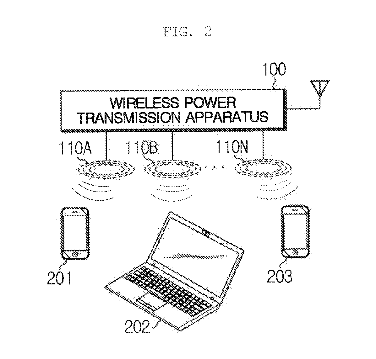
[0044]FIG. 2 is a schematic view showing a wireless power transmission apparatus according to the present disclosure, FIG. 3 is a ...


PUM


Abstract

A wireless power transmission apparatus includes at least one power transmission antenna for transmitting a wireless power signal in a magnetic resonance manner by using a resonant frequency having different bandwidths from each other; a wireless power signal generating module for generating the wireless power signal; at least one wireless power converting module for converting a power level of the wireless power signal generated by the wireless power signal generating module and having different power level conversion ranges corresponding to the bandwidth of the resonant frequency of the power transmission antenna; a multiplexer matching module for selectively connecting the wireless power converting module to a corresponding power transmission antenna; and a control unit for selectively connecting the power transmission antenna and the wireless power converting module according to a required power of a device to be charged to adjust the power level of the wireless power signal.

Description

CROSS-REFERENCE TO RELATED APPLICATION[0001]This application claims priority under 35 USC 119 (a) to Korean Patent Application No. 10-2011-0089752 filed in the Republic of Korea on Sep. 5, 2011, the entire contents of which are incorporated herein by reference.BACKGROUND OF THE DISCLOSURE[0002]1. Field of the Disclosure[0003]The present disclosure relates to an apparatus for wireless power transmission tor transmitting power to portable electronic devices or small home appliances in a wireless manner to be used tor charging a battery or operating the devices, and more particularly, to a wireless power transmission apparatus in which an antenna in charge of power transmission is configured as a multi antenna to optimize the power transmission efficiency for various devices which need charging.[0004]2. Description of the Related Art[0005]Portable electronic devices such as mobile communication terminals, PDA, PMP, and notebooks generally use rechargeable secondary batteries in order t...

Claims


Application Information

Patent Timeline
IPC IPC(8): H02J7/00
CPCH02J5/005H02J50/80H02J7/0048H02J50/12H02J50/40H03H7/38H02J50/90H02J7/0047H04B5/79H02J7/00
Inventor LEE, JI-HYUNGPARK, LAE-HYUKPARK, UN-KYOO
Owner LS CABLE & SYST LTD
Learn More