Business Form with Wristband Having Multi-Ply Image Area
a wristband and image area technology, applied in the direction of identification means, other printing materials, instruments, etc., can solve the problems of reducing the resiliency and strength of single layer or single ply wristbands, unable to compete with other printing materials, and unable to locate and read identifying information such as bar codes, etc., to achieve less expensive, less sturdy materials, and adequate performance
- Summary
- Abstract
- Description
- Claims
- Application Information
AI Technical Summary
Benefits of technology
Problems solved by technology
Method used
Image
Examples
first embodiment
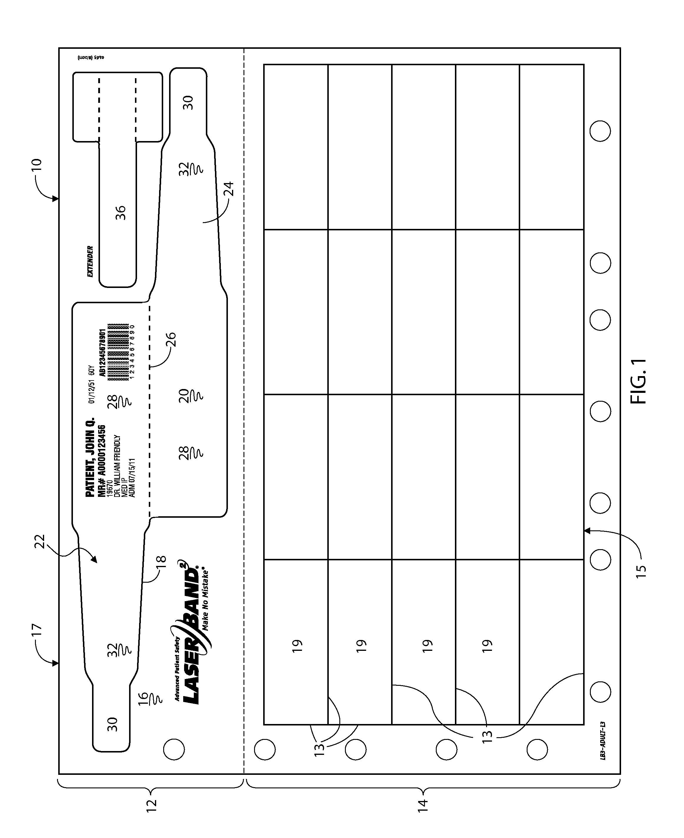
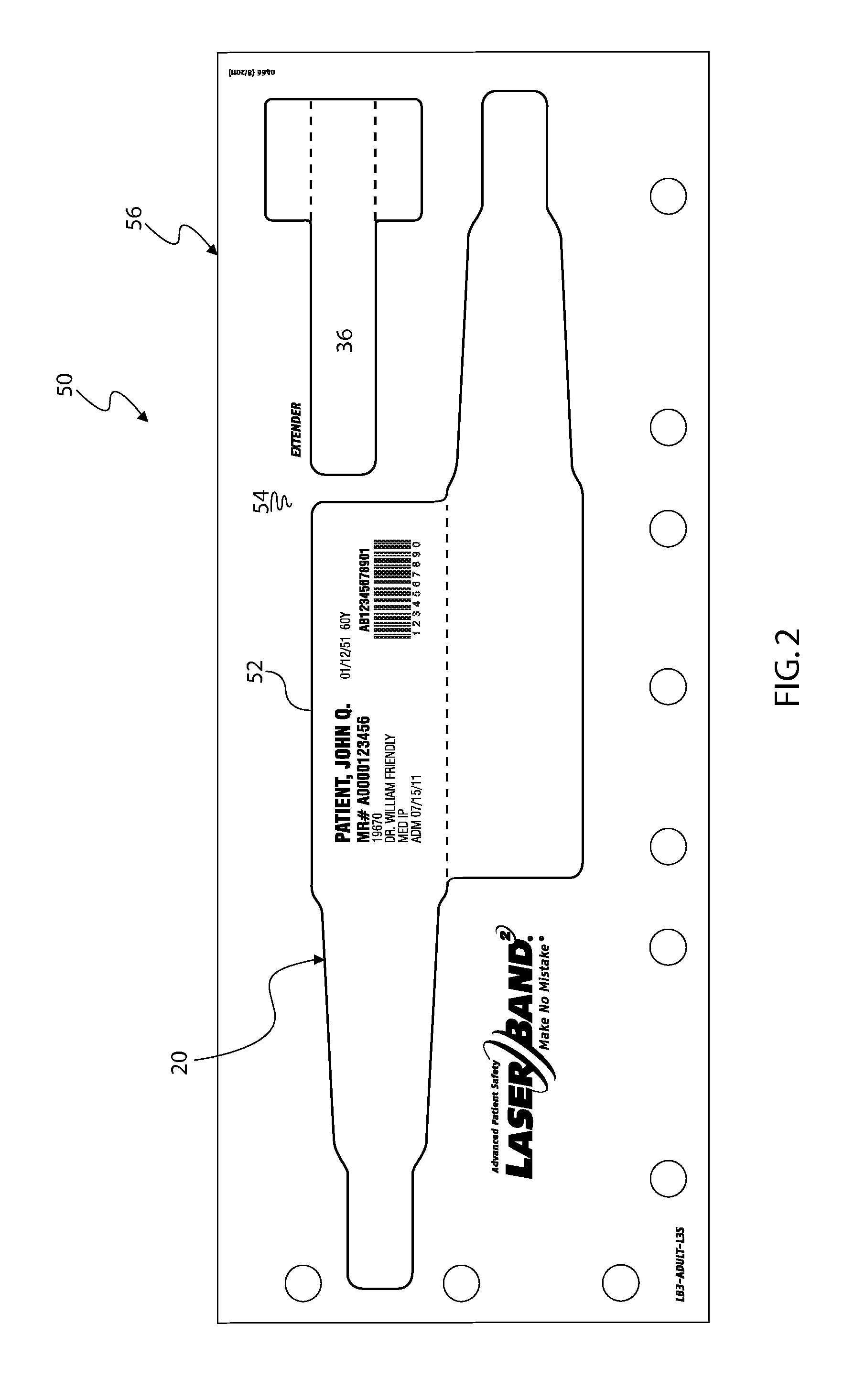
[0027]Yet another embodiment 140 as depicted in FIG. 7 discloses another different wristband 152. Wristband 152 is formed from a first die cut 154 in the top ply 156, similarly to the first wristband 20, but also includes a reinforcing or backing panel 158 formed by a second die cut 160 formed in the bottom ply 162 adhered to the panel portion 164 of wristband 152. In essence, this wristband design is a combination of the first embodiment wristband 20 with the backing panel 126 from the wristband embodiment shown in FIG. 6. Thus, wristband 152 has three layers of material instead of the two layers of material reinforcing the wristband print areas of the other embodiments. Although backing panel 158 is depicted as being formed behind the top panel portion 164, it could also be formed behind the bottom panel portion 166 of wristband 152. When separated and folded over, the backing panel is thereby sandwiched between wristband panels 164 and 166, and adhered to each of them with adhesi...
embodiment 140
[0028]A business form 169 which is a variation of the embodiment 140 is shown in FIG. 8, and includes a somewhat different wristband design 170. Wristband 170 is defined by a die cut 172 in top ply 174 and includes a top panel 176 having a pair of straps 178 extending to each of its sides, with a second panel 180 being joined to the first panel 176 with a perforated or fold line 182 therebetween. A backing panel 184 is defined by another die cut 186 in the bottom ply 188 and adhered to the top panel 176 so that as the wristband 170 is separated from the form 169 the backing panel 184 remains adhered thereto, thereby reinforcing top panel 176. Additionally, after separation, the wristband 170 is folded about fold line 182 to adhere and sandwich the backing panel 184 between the two wristband panels 176, 180. As with the wristband embodiment shown in FIGS. 6 & 7, the wristband design depicted in this FIG. 8 may be provided in the other embodiments as well. To complete this business fo...
embodiment 250
[0030]A final embodiment of the business form 250 is depicted in FIG. 10 and includes a wristband 252 formed by a die cut 254 in the top ply 256 of the bottom portion 258 of the form 250. Wristband 252 includes a pair of virtually full length panels 260 separated by a perforation or fold line 262 with a pair of adhesive coated tabs 264 extending from the opposite sides of the panels 260 so that when separated and folded over, the adhesive coated tabs 264 are situated to adhere to each other or to the back of a panel 260 to thereby attach the wristband 252 to a patient. In this embodiment 250, either panel may be imprinted with patient data as the wristband may be folded and then turned in either direction to face the printed data to the outside when wrapped around the wrist. As with other embodiments, this business form 250 includes a matrix 266 of self-adhering labels 268 defined by die cuts 270 in the top ply 256, but with this embodiment in the upper portion 272 of the form 250. ...
PUM
 Abstract
Description
Claims
Application Information
 - R&D
- Intellectual Property
- Life Sciences
- Materials
- Tech Scout
- Unparalleled Data Quality
- Higher Quality Content
- 60% Fewer Hallucinations
Browse by: Latest US Patents, China's latest patents, Technical Efficacy Thesaurus, Application Domain, Technology Topic, Popular Technical Reports.
© 2025 PatSnap. All rights reserved.Legal|Privacy policy|Modern Slavery Act Transparency Statement|Sitemap|About US| Contact US: help@patsnap.com


