
Method for 3D visual mapping using 3D stereoscopic video content

a technology of stereoscopic video content and visual mapping, applied in the field of 3d image projection, can solve the problem of limitations of 3d projection mapping

Inactive Publication Date: 2013-02-21
SOPHRIN JOSHUA
View PDF1 Cites 8 Cited by
  • Summary
  • Abstract
  • Description
  • Claims
  • Application Information

AI Technical Summary

Benefits of technology

The present invention is about a method for creating a 3D visual map using 3D stereoscopic video content. The method involves recording a live recorded-rendered 2D perspective white image that is mapped to an architectural or other 3D object. This creates a 2D perspective mask that covers the abstract surface areas of the architectural structure or 3D object. The mask is then separated into sub-masks that are used to mask areas around the 3D stereoscopic video content. The result is a 2D masked-mapped stereoscopic 3D video content that can be played on 3D stereoscopic projectors. The invention allows for the synchronization of projectors and ensures that the 3D content is played on the correct surfaces.

Problems solved by technology

However, 3D projection mapping has its limitations.

Method used


Image

  • Method for 3D visual mapping using 3D stereoscopic video content
  • Method for 3D visual mapping using 3D stereoscopic video content
  • Method for 3D visual mapping using 3D stereoscopic video content

Examples


Embodiment Construction

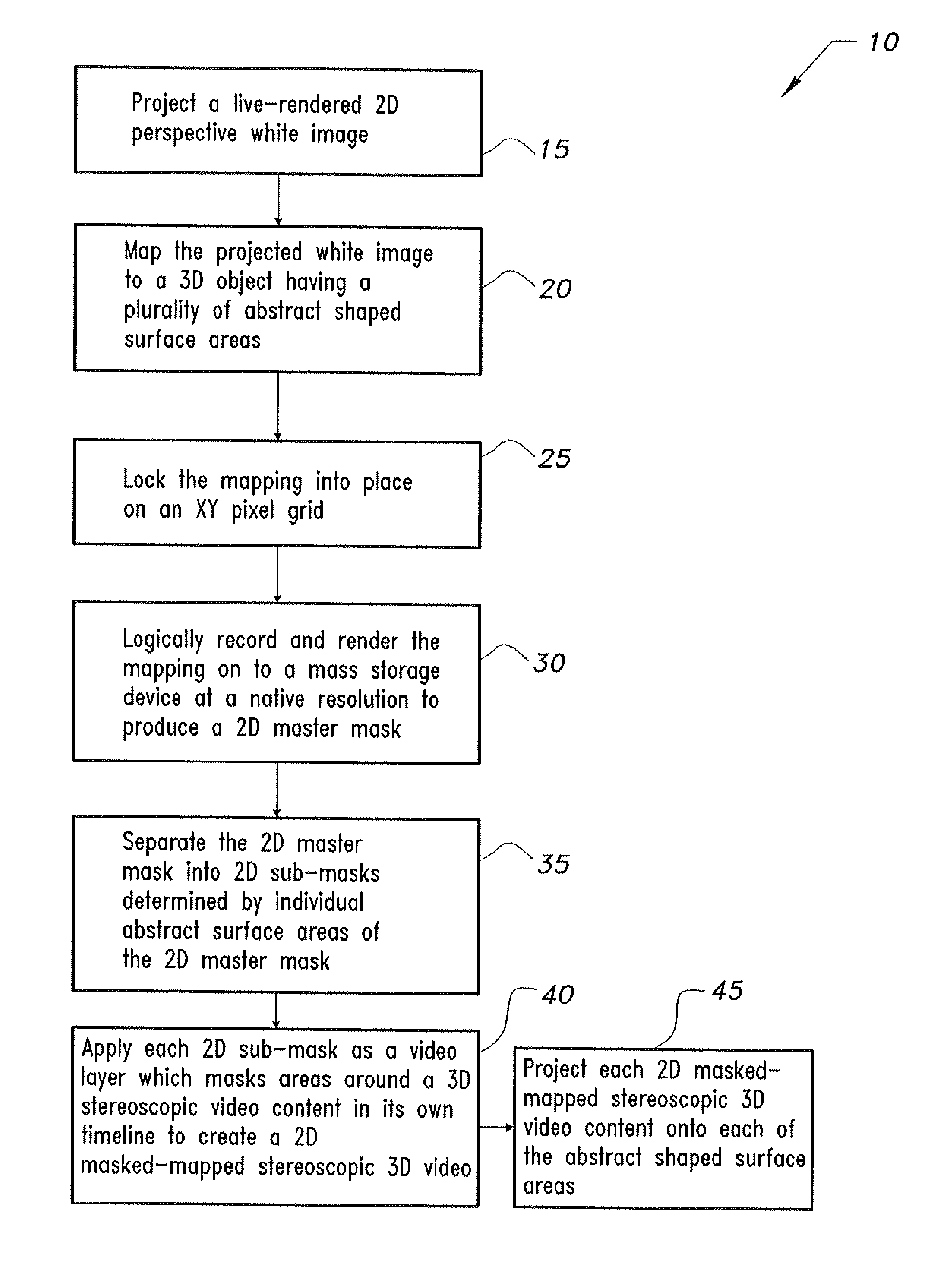
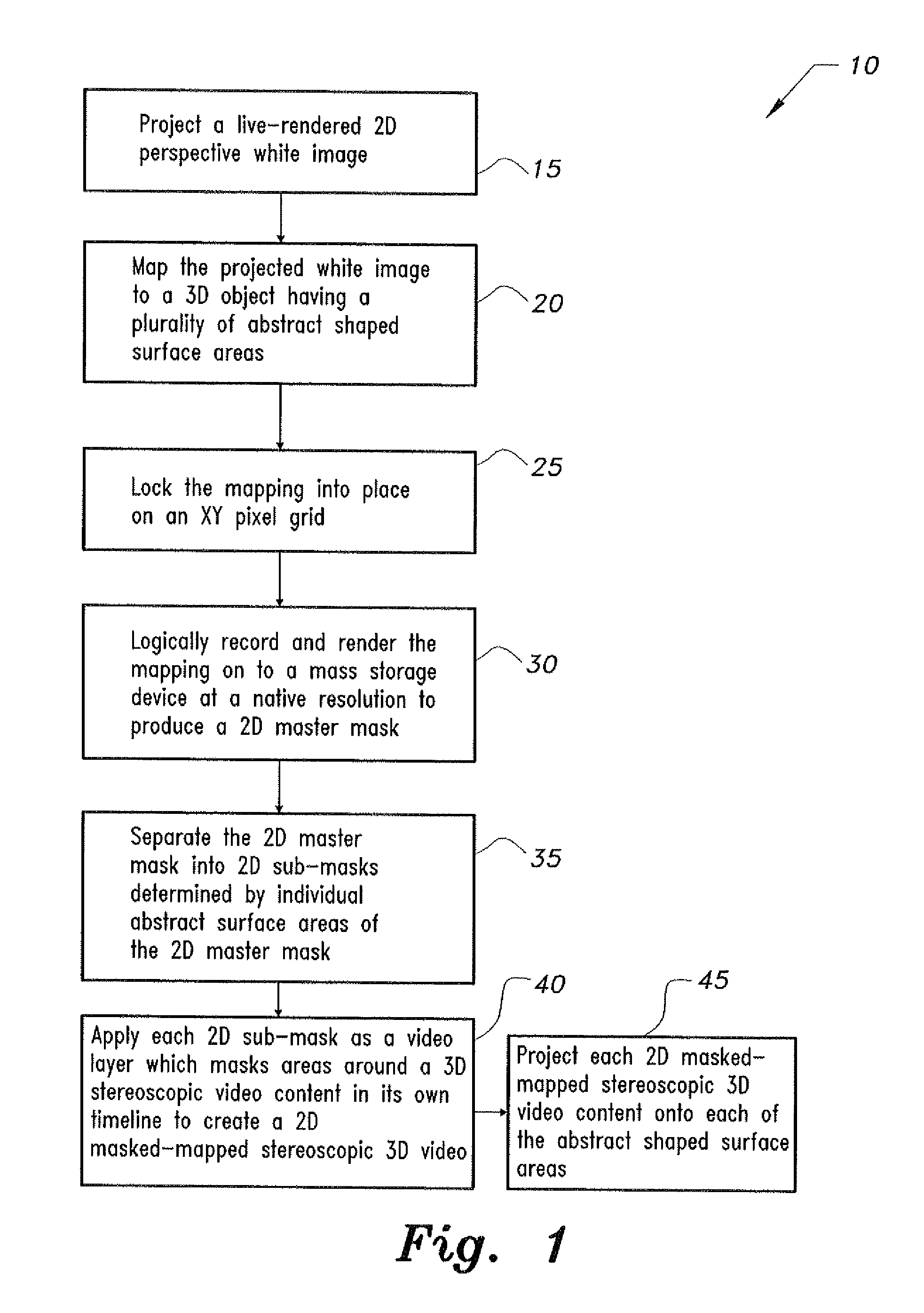
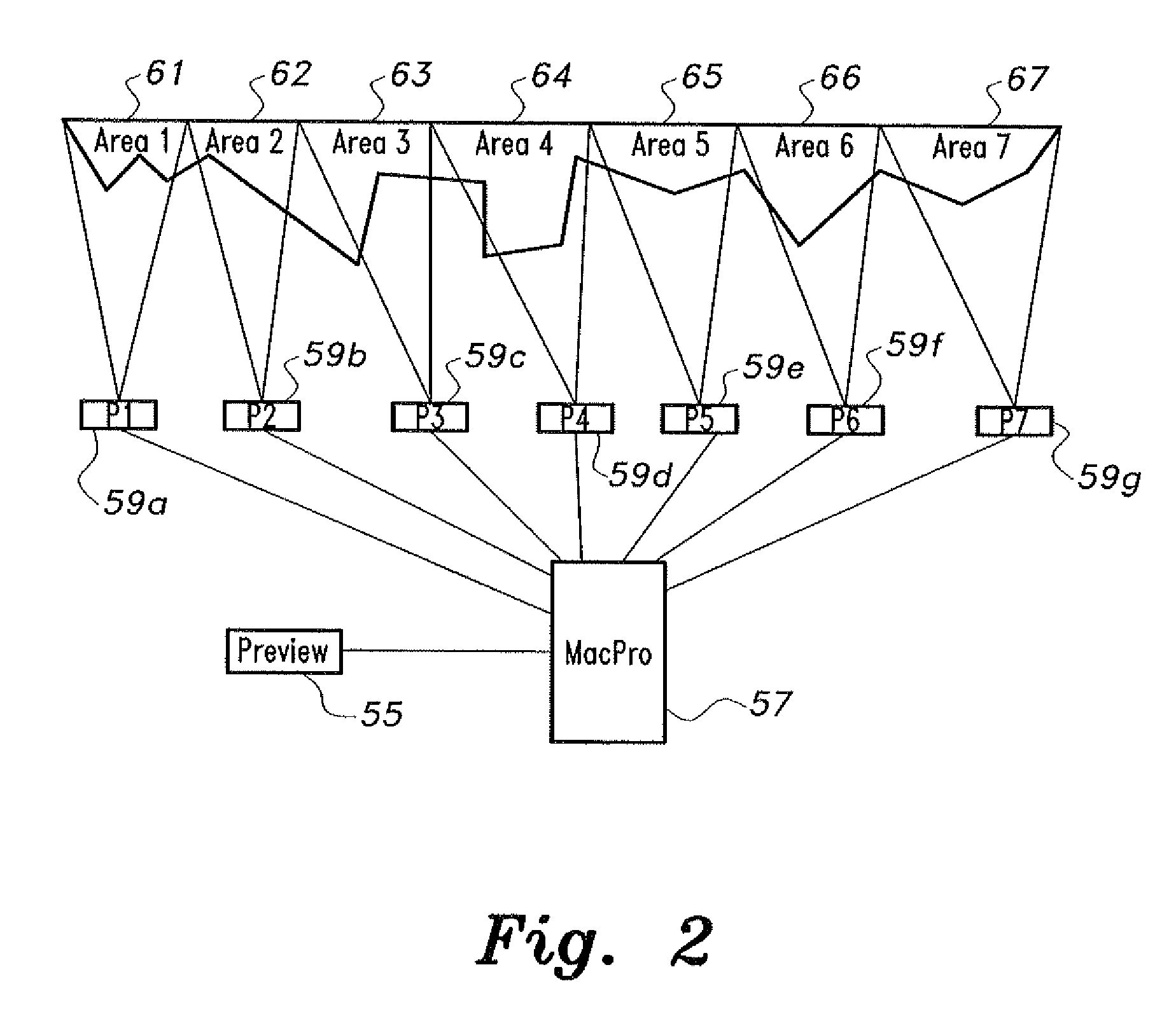
[0019]The method for 3D visual mapping using 3D stereoscopic video content includes recording a live-rendered 2D perspective white image while mapping the white image to an architectural or other 3D object having a number of abstract shaped surface areas to create a 2D perspective mask fitting the architectural structure or other 3D object. The abstract surface areas are covered by as many projectors as the number of abstract shaped surface areas, the projectors being under computer control.

[0020]The mapping is locked into place on an XY pixel grid, and then the entire project is logically recorded-rendered onto a hard drive at a native resolution to produce a 2D master mask. The 2D master mask is separated into sub-masks determined by the individual surface areas of the 2D master mask. Each 2D sub-mask is then applied as a video layer and used to mask areas around 3D stereoscopic video content in its timeline. This 2D masked-mapped stereoscopic 3D video content is then played on 3D...


PUM


Abstract

The method for 3D visual mapping using 3D stereoscopic video content records live 2D perspective white images mapped to architectural or other 3D objects having abstract shaped surfaces to create 2D perspective masks fitting the surface shapes. Each abstract surface area is covered by a dedicated projector and controller. The mapping is locked into place on a pixel grid, the project being logically recorded-rendered onto a hard drive at native resolution to produce a 2D master mask, which is separated into sub-masks determined by the individual areas of the 2D master mask. Each 2D sub-mask is applied as a video layer and used to mask areas around 3D stereoscopic video content in its timeline. The 2D masked-mapped stereoscopic 3D video can be played on 3D stereoscopic projectors. A common clock synchronizes the processors for playback of the 3D content on the 3D surface areas.

Description

CROSS-REFERENCE TO RELATED APPLICATION[0001]This application claims the benefit of U.S. Provisional Patent Application Ser. No. 61 / 523,806, filed Aug. 15, 2011.BACKGROUND OF THE INVENTION[0002]1. Field of the Invention[0003]The present invention relates to 3D image projection, and particularly to a method for 3D visual mapping using 3D stereoscopic video content that projects 2D-mapped 3D images on to architectural or other 3D surfaces.[0004]2. Description of the Related Art[0005]Projection mapping is the accurate alignment of projected images with architectural features of buildings, stage sets, or other 3 dimensional (3D) objects. Projection mapping onto buildings is done by the use of high-power projectors. Video jockeys (VJs) are experimenting with actual real 3D objects and mapping projected video images onto the actual 3D objects, This process is called 3D projection mapping, For example, using MODUL8 as the mixer-compositor and a projector, an image can be projected onto a 3D...

Claims


Application Information

Patent Timeline
Patent Type & Authority Applications(United States)
IPC IPC(8): H04N13/04
CPCH04N9/3185H04N9/3147H04N9/3194
Inventor SOPHRIN, JOSHUA
Owner SOPHRIN JOSHUA
Learn More