
Conical Water-Equivalent Phantom Design for Beam Hardening Correction in Preclinical Micro-CT

Inactive Publication Date: 2013-01-31
SIEMENS MEDICAL SOLUTIONS USA INC
View PDF11 Cites 7 Cited by
  • Summary
  • Abstract
  • Description
  • Claims
  • Application Information

AI Technical Summary

Benefits of technology

The present invention relates to a phantom for beam hardening correction in computed tomography. The phantom includes a calibration tip attached to a portion of the phantom that has a diameter that increases incrementally from the proximal end to the distal end. The phantom is scanned and the image of it reconstructed, using which an algorithm is generated to calculate the beam hardening coefficients. These coefficients are then used to reconstruct the image and calculate the expected attenuation coefficient. The technical effects of this invention include improved accuracy and reliability in computed tomography imaging.

Problems solved by technology

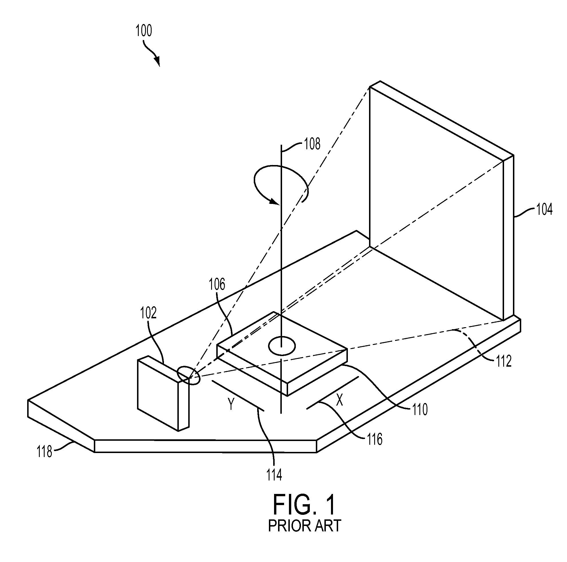
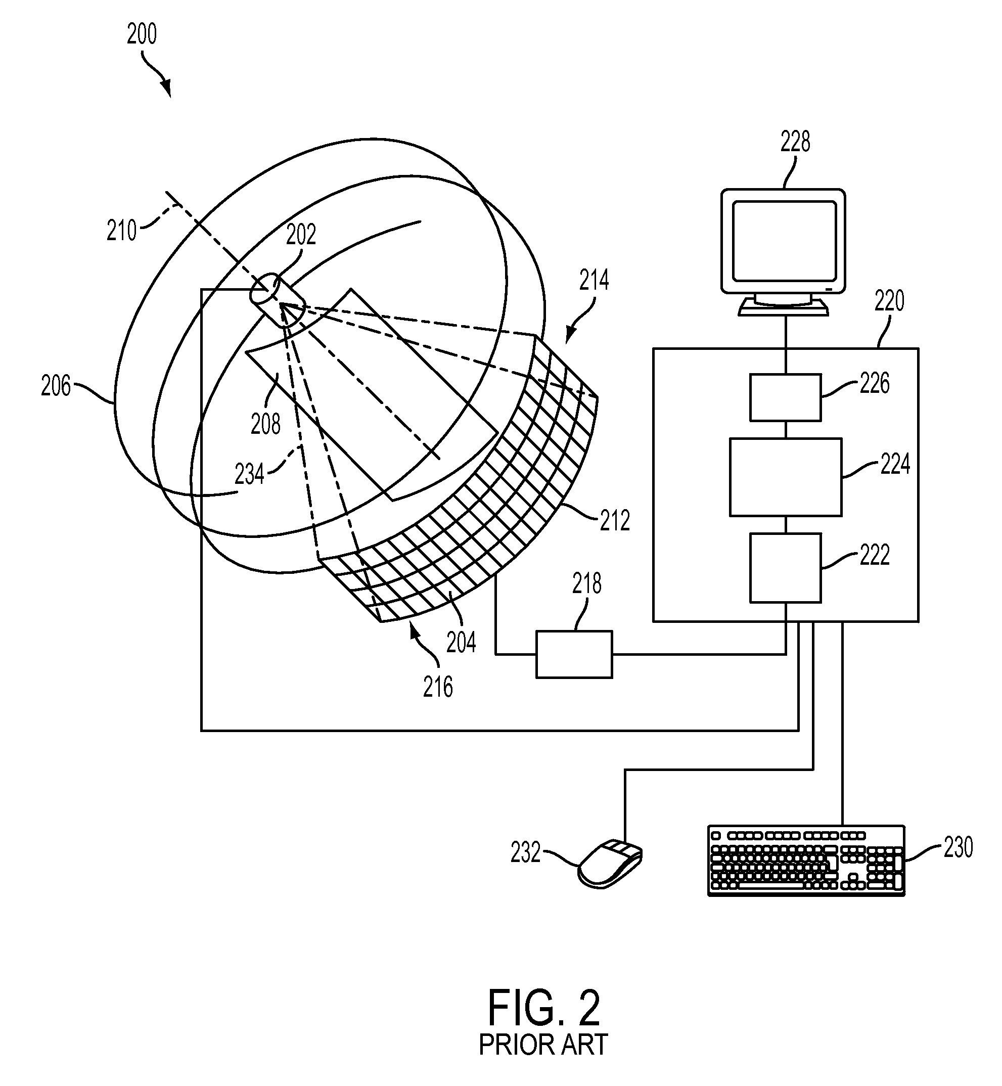
Images acquired from the scanners depicted in FIGS. 1 and 2 can suffer from “beam hardening.” Beam hardening is a general problem in high-energy imaging.
Thus, failure to correct for beam hardening effects may cause incorrect estimation of material densities.
This is particularly a problem when imaging high-density materials, such as bone.
While the x-ray photons generated by the x-ray source are polychromatic, reconstruction algorithms usually assume the attenuation coefficient of the material is invariant with the energy of the incident photons, thus creating the artifacts and leading to degraded image quality in the reconstructed images.
Further, the size of the phantom limits the range of coefficients that can be used (and the size of a subsequent object that would utilize those coefficients).
Sometimes the correction algorithm does not adequately account for the phantom material.

Method used


Image

  • Conical Water-Equivalent Phantom Design for Beam Hardening Correction in Preclinical Micro-CT
  • Conical Water-Equivalent Phantom Design for Beam Hardening Correction in Preclinical Micro-CT
  • Conical Water-Equivalent Phantom Design for Beam Hardening Correction in Preclinical Micro-CT

Examples


Embodiment Construction

[0035]In the following description, numerous specific details are set forth to provide a more thorough understanding of the invention. As will be apparent to those skilled in the art, however, various changes using different configurations may be made without departing from the scope of the invention. In other instances, well-known features have not been described in order to avoid obscuring the invention. Thus, the invention is not considered limited to the particular illustrative embodiments shown in the specification and all such alternate embodiments are intended to be included in the scope of the appended claims.

[0036]Embodiments of the invention, as disclosed herein, can be used with various imaging systems. For example, although embodiments of the invention are described herein as being used in conjunction with a micro-computed tomography (“micro-CT”) system those descriptions are for illustrative purposes only and not intended in any way to limit the scope of the invention. ...


PUM


Abstract

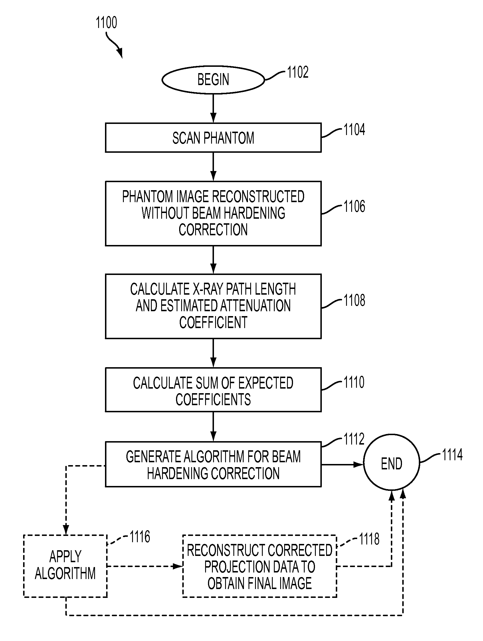
Apparatuses, methods, and computer-readable mediums are provided that utilize a phantom to correct attenuation due to beam hardening. The phantom includes a calibration tip attached to a proximal end of a portion. The portion has a diameter that increases incrementally from the proximal end of the portion towards a distal end of the portion (e.g., a substantially conical shape, a substantially convex shape, a substantially concave shape, or a series of adjacent steps). In another embodiment, a method is provided in which the phantom is scanned and an image of the phantom is reconstructed. Thereafter, an x-ray path length and estimated attenuation coefficient are calculated. A sum of expected coefficients are also calculated. The calculations are used to generate an algorithm for beam hardening coefficients.

Description

CROSS-REFERENCE TO RELATED APPLICATION[0001]This application claims the benefit of U.S. provisional application entitled “A Conical Water-equivalent Phantom Design for Beam Hardening Correction in Preclinical Micro-CT,” filed Jul. 27, 2011, and assigned U.S. Ser. No. 61 / 512,046, the entire disclosure of which is hereby incorporated by reference.BACKGROUND[0002]1. Field of the Invention[0003]Embodiments of the present invention generally relate to a computed tomography and more specifically to phantoms, methods, systems, and computer-readable mediums for beam hardening correction.[0004]2. Description of the Related Art[0005]Microtomography (commonly known as Industrial CT Scanning), like tomography, uses x-rays to create cross-sections of a 3D-object that later can be used to recreate a virtual model without destroying the original model. The term micro is used to indicate that the pixel sizes of the cross-sections are in the micrometer range. These pixel sizes have also resulted in ...

Claims


Application Information

Patent Timeline
IPC IPC(8): G01D18/00
CPCA61B6/032A61B6/508A61B6/583A61B6/5258A61B6/5205
Inventor YAN, SHIKUIDENG, JUNJUNBRUCKBAUER, THOMAS
Owner SIEMENS MEDICAL SOLUTIONS USA INC
Learn More