
Surgical head holder and surgical accessories for use with same

a head holder and head technology, applied in the field of surgical accessories, can solve the problems of limiting the ability of the retractor apparatus to be close to the surgical wound, the attachments are relatively large, and the system that connects the headrest to the operating table does not specifically allow for rigid connection of the various brain retractor systems, so as to achieve the effect of efficient and simultaneous use of surgical accessories without sacrificing functionality

Active Publication Date: 2013-01-24
SKLAR FREDERICK H
View PDF14 Cites 32 Cited by
  • Summary
  • Abstract
  • Description
  • Claims
  • Application Information

AI Technical Summary

Benefits of technology

The patent describes a surgical head holder and accessories that can be used when operating on the brain. The holder has a horseshoe-shaped head support with adjustable wings and a gel pad. It can be attached to a table for stability. The accessories include a retractor, image guidance hardware frame, and a light and mirror assembly. The technical effect of this invention is a rigid connection of various brain retractor systems and other surgical accessories during brain surgery, allowing for efficient and simultaneous use of multiple tools without sacrificing functionality.

Problems solved by technology

At present, systems that connect surgical headrests to the operating table do not specifically allow for rigid connection of various brain retractor systems.
These horizontal connecting rods can interfere with the placement of image guidance hardware and can limit how close the retractor apparatus can be to the surgical wound.
Other existing systems allow rigid attachment of image guidance connection hardware to traditional three pin headrest devices, but these attachments are relatively large, somewhat awkward to use, and in close proximity to the patient's head.

Method used


Image

  • Surgical head holder and surgical accessories for use with same
  • Surgical head holder and surgical accessories for use with same
  • Surgical head holder and surgical accessories for use with same

Examples


Embodiment Construction

[0017]While the making and using of various embodiments of the present invention are discussed in detail below, it should be appreciated that the present invention provides many applicable inventive concepts which can be embodied in a wide variety of specific contexts. The specific embodiments discussed herein are merely illustrative of specific ways to make and use the invention, and do not delimit the scope of the present invention.

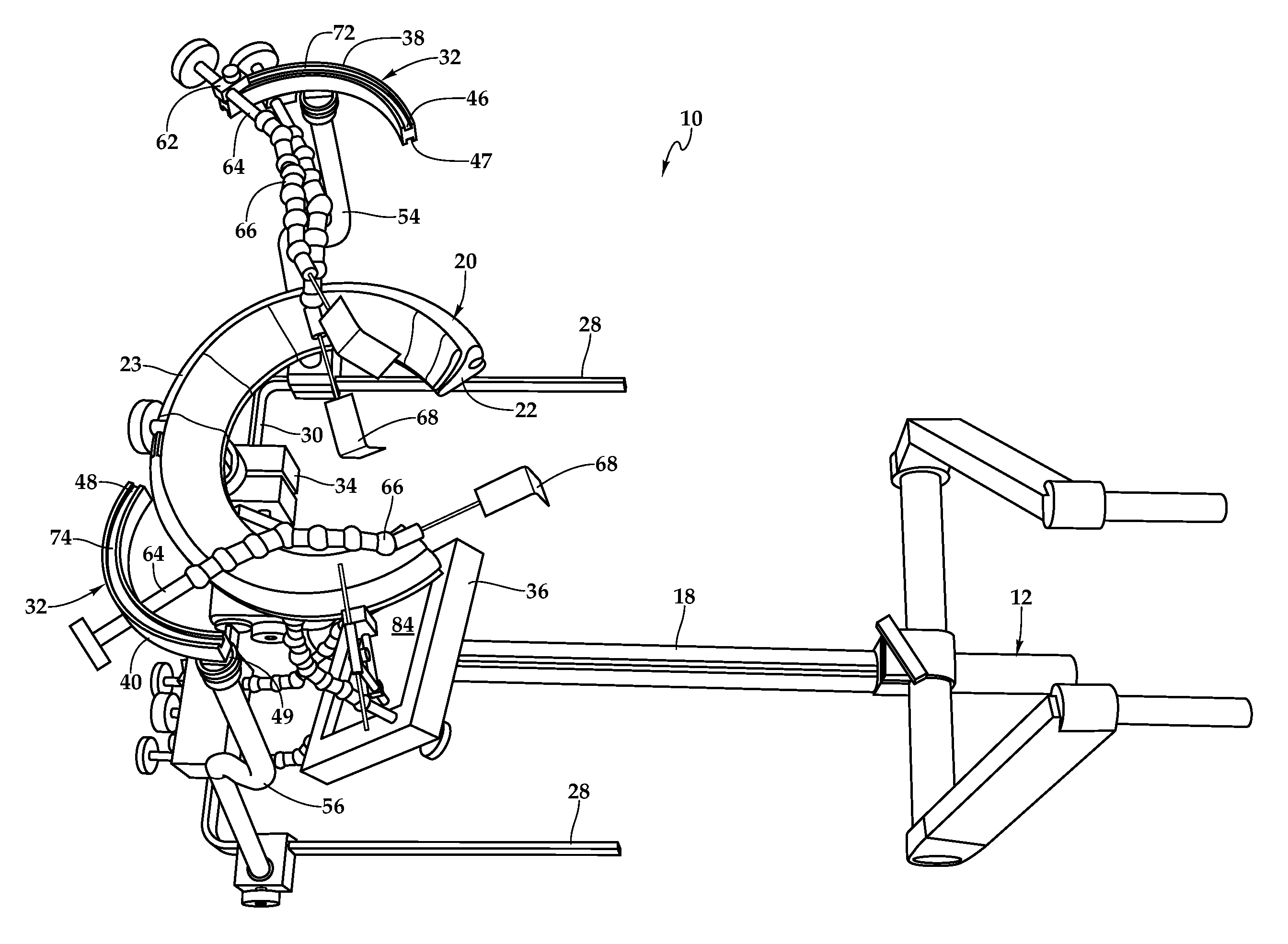
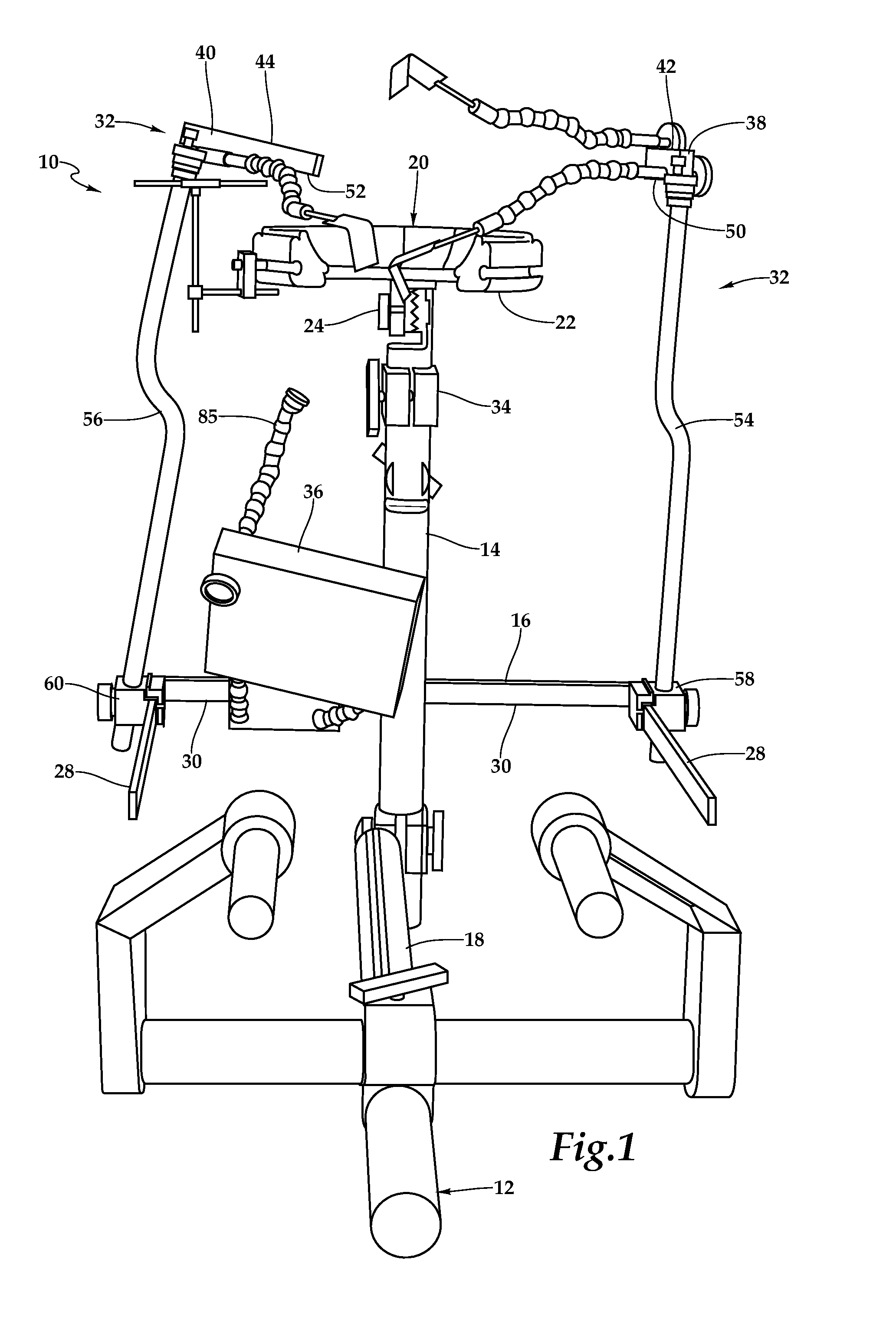
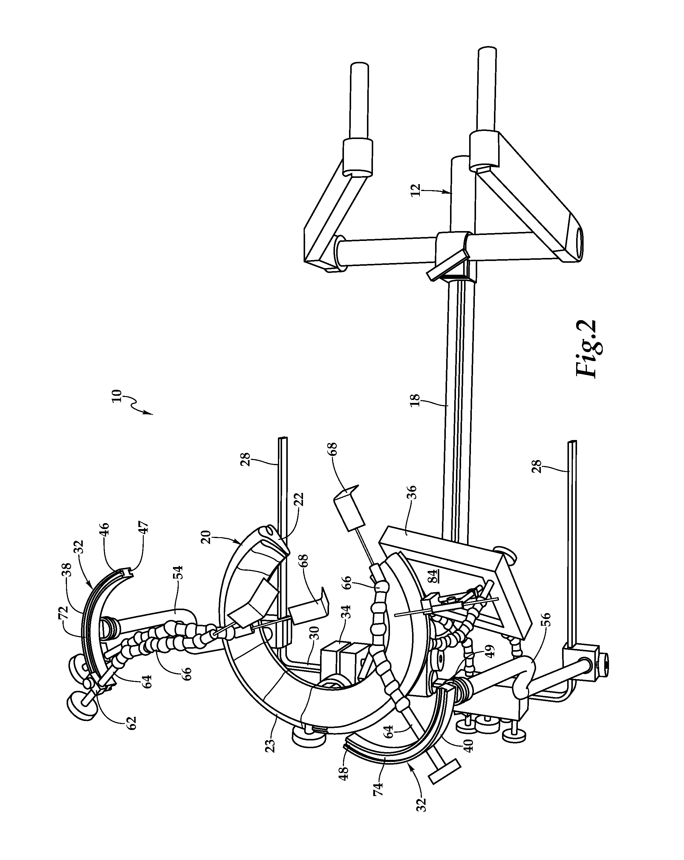
[0018]Referring initially to FIGS. 1 through 4, therein is depicted one embodiment of a surgical head holder for skull stabilization during neurosurgical and orthopedic procedures, which is schematically illustrated and designated 10. A table attachment 12 is adapted to be selectively and rigidly coupled to an operating table. The table attachment 12 includes an adjustable vertical body 14, a horizontal generally u-shaped bar 16 adjustably intersecting therewith, and an attachment member 18 extending therefrom for coupling to the operating table in a st...


PUM


Abstract

A surgical head holder and accessories for use with the same are disclosed. In one embodiment, a horseshoe shaped head support includes two wings pivotally coupled that adjust the angle therebetween. Arcuate base members are coupled to the wings to accept a plurality of placement subassemblies, which are circumferentially adjustably positioned and secured within the channels. Each placement subassembly is configured to receive a skull pin and provide adjustable horizontal, vertical, and angular positioning of the skull pin with respect to the arcuate base. A table attachment supports the horseshoe shaped head support and is adapted to be selectively and rigidly coupled to an operating table. The table attachment includes a vertical body, a horizontal generally u-shaped bar adjustably intersecting therewith, and an attachment member extending therefrom for coupling to the operating table. Various neurosurgical accessories may be rigidly coupled to the table attachment.

Description

PRIORITY STATEMENT & CROSS-REFERENCE TO RELATED APPLICATIONS[0001]This application claims priority from co-pending U.S. Patent Application No. 61 / 510,689, entitled “Pediatric Headrest and Accessories for Use with Same” and filed on Jul. 22, 2011, in the name of Frederick H. Sklar; which is hereby incorporated by reference for all purposes.TECHNICAL FIELD OF THE INVENTION[0002]This invention relates, in general, to the field of surgical appliances and, in particular, to a surgical head holder and surgical accessories for use with the same during surgical operations on the brain.BACKGROUND OF THE INVENTION[0003]At present, systems that connect surgical headrests to the operating table do not specifically allow for rigid connection of various brain retractor systems. Some self-retaining retractor systems are designed to be attached directly to standard three pin headrests with pressure clamps that, when used, gather draping material into the clamp and can therefore become dislodged or ...

Claims


Application Information

Patent Timeline
Patent Type & Authority Applications(United States)
IPC IPC(8): A61G15/00
CPCA61B19/203A61G13/121A61B90/14F04C2270/0421
Inventor SKLAR, FREDERICK H.
Owner SKLAR FREDERICK H
Learn More