
Dynamic antenna sharing

a technology of dynamic sharing and antennas, applied in the field of communication systems, can solve the problems of many manufacturers of mobile communication devices that cannot justify the additional cost and/or space required to implement separate antennas for lte, wi-fi, bluetooth communication,

Inactive Publication Date: 2012-12-27
QUALCOMM INC
View PDF8 Cites 73 Cited by
  • Summary
  • Abstract
  • Description
  • Claims
  • Application Information

AI Technical Summary

Problems solved by technology

However, due to cost and / or space concerns, many mobile devices employ a single shared antenna for both Wi-Fi and Bluetooth signaling.
Thus, although it is preferable to use separate (e.g., dedicated) antennas for Wi-Fi, Bluetooth, and LTE communications, many manufacturers of mobile communication devices have not been able to justify the additional cost and / or space required to implement separate antennas for LTE, Wi-Fi, and Bluetooth communications.

Method used


Image

  • Dynamic antenna sharing
  • Dynamic antenna sharing
  • Dynamic antenna sharing

Examples


Embodiment Construction

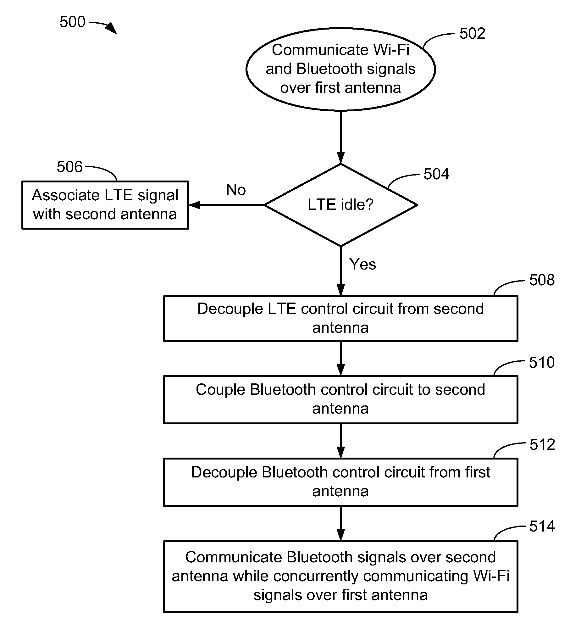
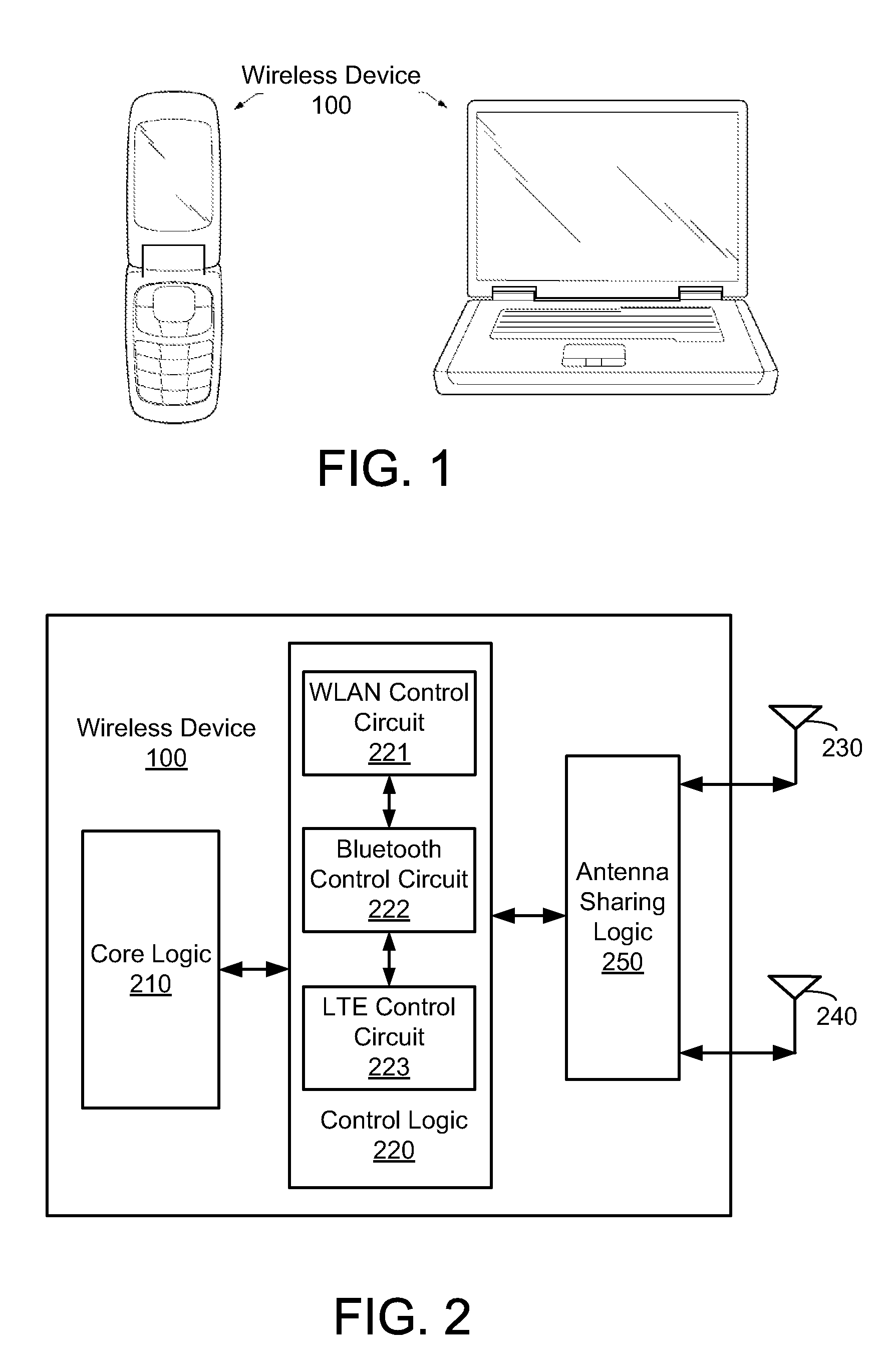
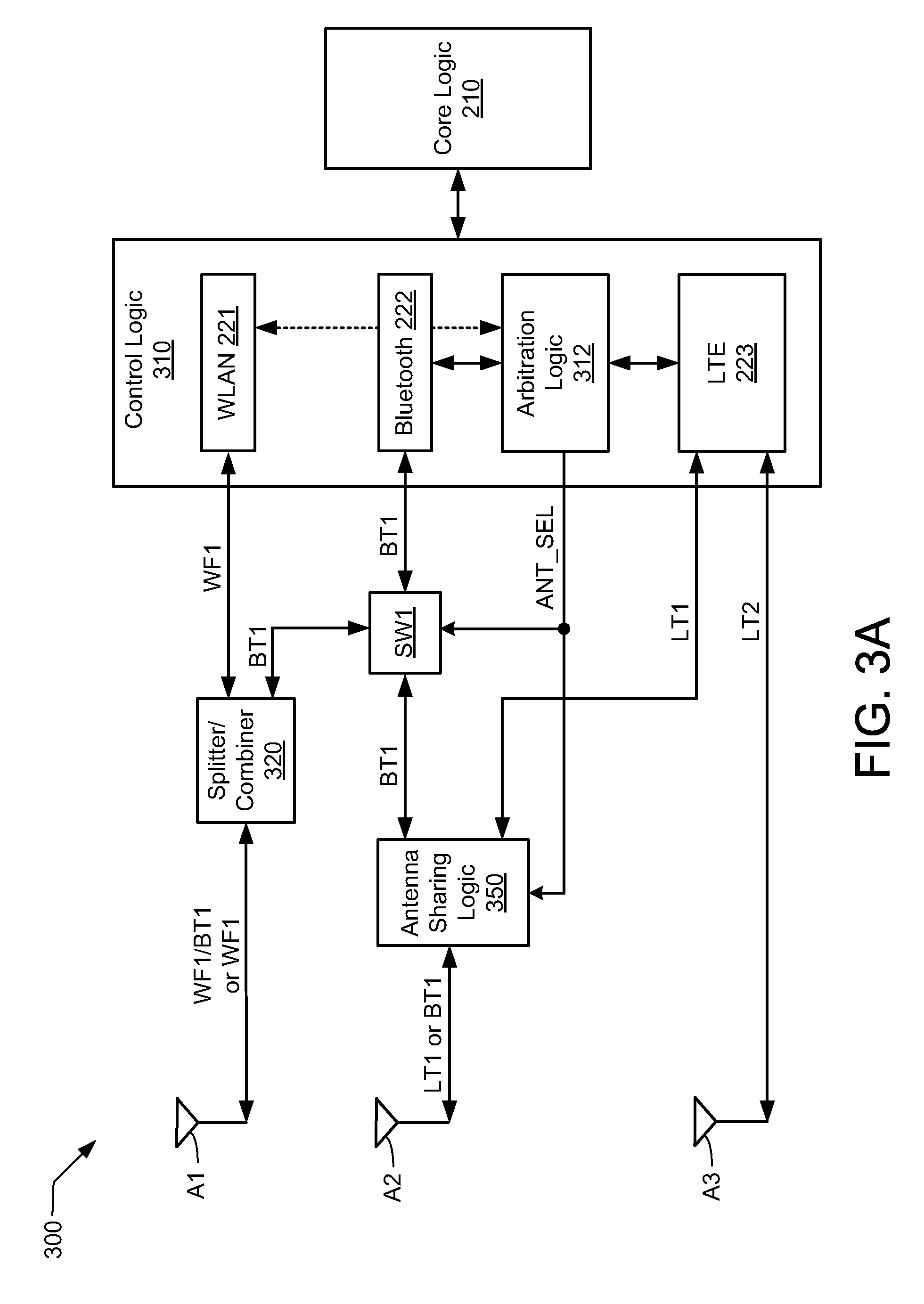
[0017]The present embodiments are discussed below in the context of dynamically sharing antennas in a mobile communication device capable of transmitting and receiving Wi-Fi, Bluetooth, and long-term evolution (LTE) signals for simplicity only. It is to be understood that the present embodiments are equally applicable for dynamically sharing antennas used for transmitting signals of other various wireless standards or protocols. In the following description, numerous specific details are set forth such as examples of specific components, circuits, software and processes to provide a thorough understanding of the present disclosure. Also, in the following description and for purposes of explanation, specific nomenclature is set forth to provide a thorough understanding of the present embodiments. However, it will be apparent to one skilled in the art that these specific details may not be required to practice the present embodiments. In other instances, well-known circuits and device...


PUM


Abstract

A mobile communication device capable of dynamically sharing antennas is disclosed. The mobile communication device includes a wireless local area network (WLAN) control circuit to generate a Wi-Fi signal, a Bluetooth control circuit to generate a Bluetooth signal, and a cellular control circuit to generate a cellular data signal. The Wi-Fi and Bluetooth control circuits are coupled to a first antenna, while the cellular control signal is coupled to a second antenna. The mobile communication device further includes an antenna sharing logic coupled between the control circuits and the first and second antennas. The antenna sharing logic is configured to selectively couple either the Wi-Fi control circuit or the Bluetooth control circuit to the second antenna based, at least in part, on a level of activity of the cellular control circuit.

Description

CROSS-REFERENCE TO RELATED APPLICATIONS[0001]This application claims the benefit under 35 USC 119(e) of the co-pending and commonly owned U.S. Provisional Application No. 61 / 501,679 entitled “DYNAMIC ANTENNA SHARING” filed on Jun. 27, 2011, the entirety of which is incorporated herein by reference.TECHNICAL FIELD[0002]The present embodiments relate generally to communication systems, and specifically to the dynamic sharing of antennas.BACKGROUND OF RELATED ART[0003]Many wireless devices are capable of wireless communication with other devices using wireless local area network (WLAN) signals, Bluetooth (BT) signals, and / or cellular signals. For example, many laptops, netbook computers, mobile phones, and tablet devices use WLAN signals (also commonly referred to as Wi-Fi signals) to wirelessly connect to networks such as the Internet and / or private networks, and use Bluetooth signals to communicate with local BT-enabled devices such as headsets, printers, scanners, and the like. Wi-F...

Claims


Application Information

Patent Timeline
IPC IPC(8): H04W88/06H04B7/00
CPCH04B1/406H04B1/0057H04W88/06H04B1/40
Inventor HUSTED, PAULHIRSCH, OLAF
Owner QUALCOMM INC
Learn More