Vibration isolation structure
a technology of vibration isolation and composite laminated components, which is applied in the direction of machine supports, mechanical equipment, portable frames, etc., can solve the problems of insufficient hydrostatic stress reduction, damage that is easily sustained, and deformation of so as to achieve effective suppression of damage to the composite laminated member
- Summary
- Abstract
- Description
- Claims
- Application Information
AI Technical Summary
Benefits of technology
Problems solved by technology
Method used
Image


Examples
first exemplary embodiment
Vibration Isolation Structure Configuration
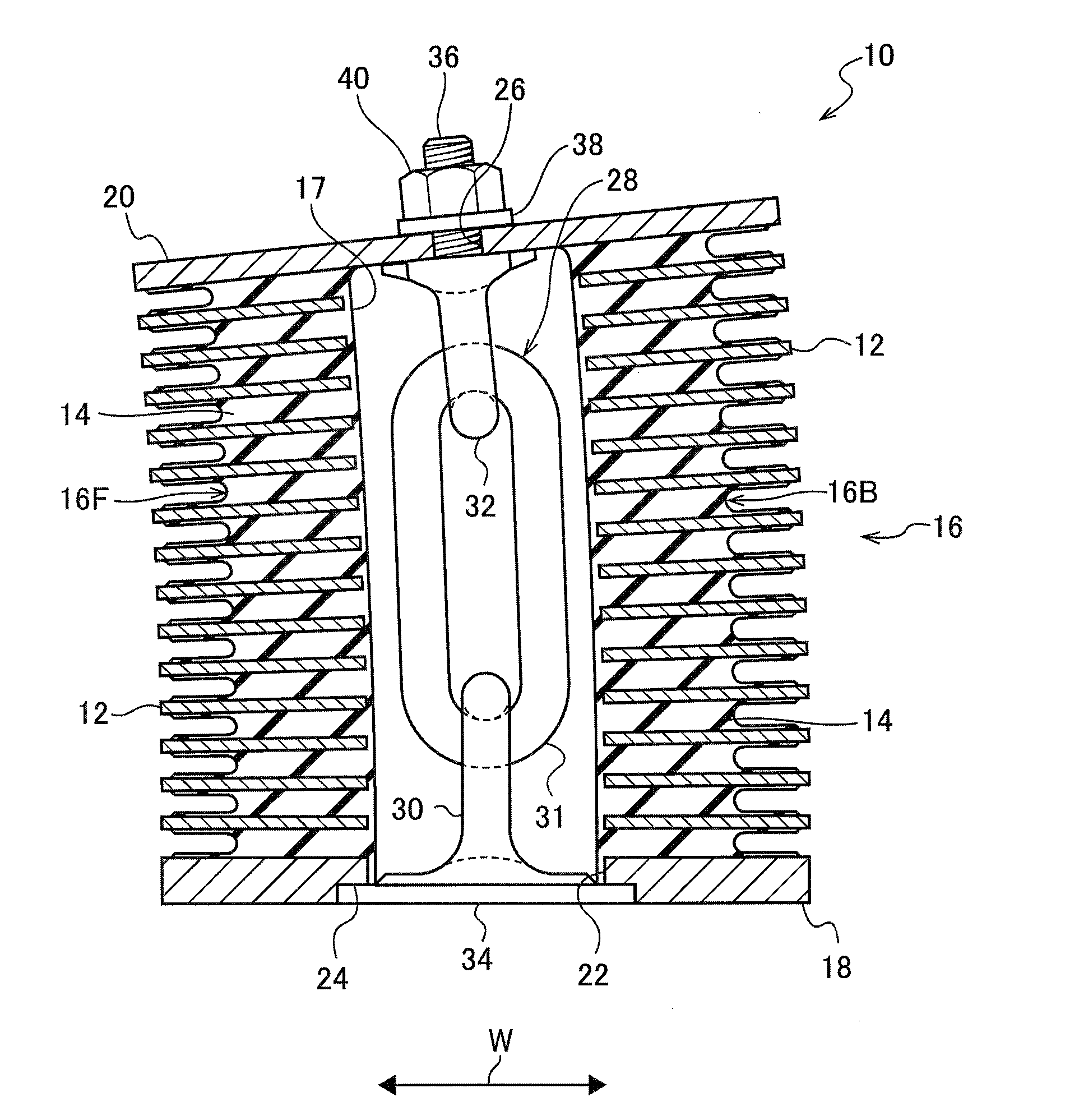
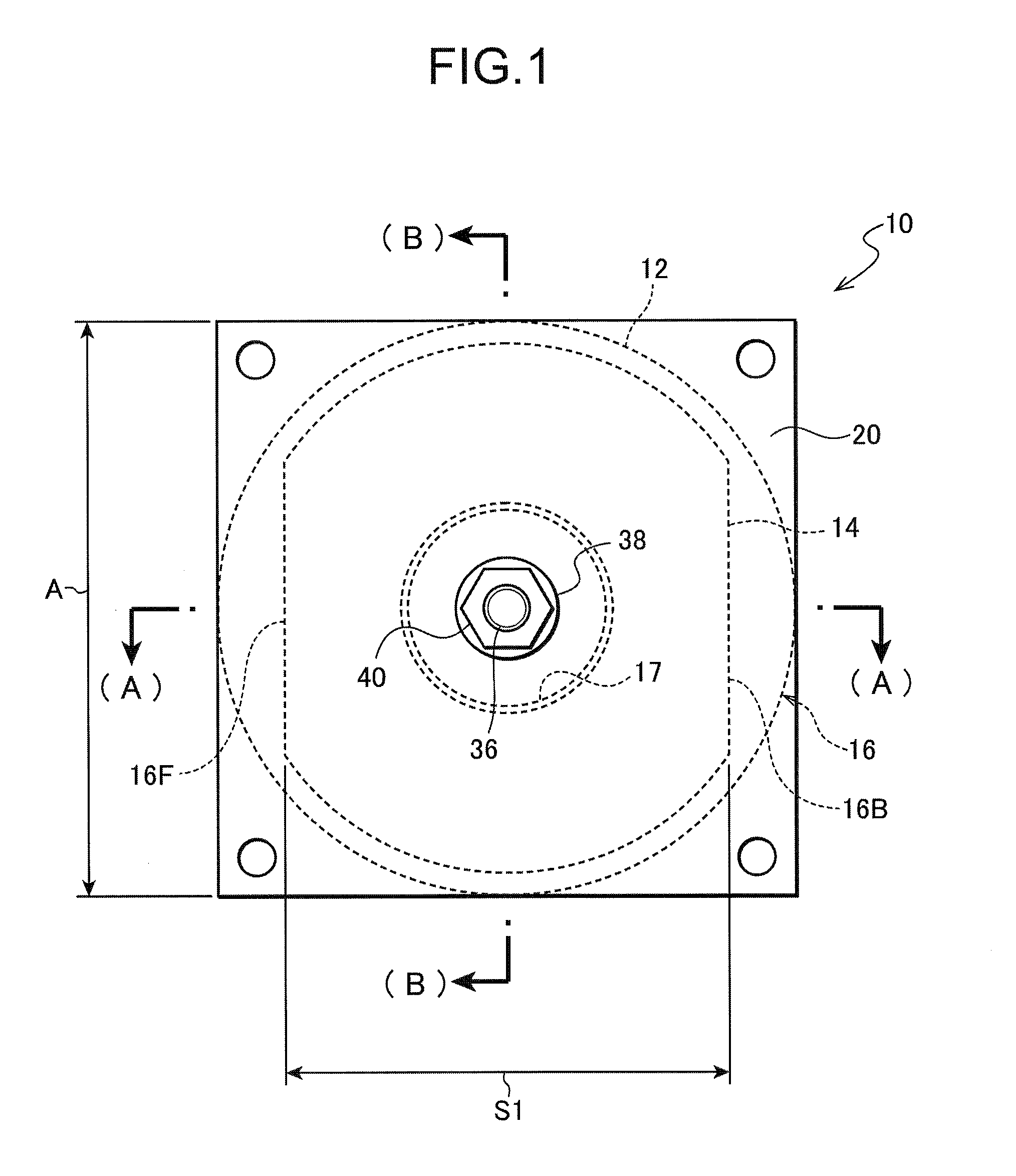
[0038]FIG. 1 and FIG. 2A and FIG. 2B illustrate a vibration isolation structure according to a first exemplary embodiment of the present invention. A vibration isolation structure 10 includes a laminated rubber body 16 that is a composite laminated member formed from alternately stacked hard plates 12 that can be considered in practice to be rigid bodies and rubber plates 14 with viscoelastic characteristics. The laminated rubber body 16 is formed in a thick substantially circular cylinder shape, with a circular column shaped hollow section 17 provided at a central face portion of the laminated rubber body 16 so as to pierce through in the laminated rubber body 16 stacking direction (the arrow L direction). The laminated rubber body 16 is configured by bonding together the hard plates 12 and the rubber plates 14 using vulcanization.
[0039]The hard plates 12 are circular plate shaped. When viewed along the stacking direction L of the laminate...
second exemplary embodiment
Vibration Isolation Structure Configuration
[0057]FIG. 4 to FIG. 6 illustrate a vibration isolation structure according to a second exemplary embodiment of the present invention. Note that portions of a vibration isolation structure 50 according to the present exemplary embodiment similar to those of the vibration isolation structure 10 according to the first exemplary embodiment are allocated the same reference numbers and further explanation thereof is omitted.
[0058]The points where the vibration isolation structure 50 according to the present exemplary embodiment differ from the vibration isolation structure 10 according to the first exemplary embodiment are in that, as viewed from the stacking direction L, the hard plates are formed in a similar shape to the rubber plates 14 in the first exemplary embodiment, and the rubber plates are formed in a similar shape to the hard plates 12 of the first exemplary embodiment.
[0059]The vibration isolation structure 50 of the present exempla...
third exemplary embodiment
Vibration Isolation Structure Configuration
[0069]FIG. 7 to FIG. 9 illustrate a vibration isolation structure according to a third exemplary embodiment of the present invention. Note that portions of a vibration isolation structure 60 according to the present exemplary embodiment similar to those of the vibration isolation structures 10, 50 of the first and second exemplary embodiments are allocated the same reference numerals and further explanation thereof is omitted.
[0070]The points in which the vibration isolation structure 60 according to the present exemplary embodiment differs from the vibration isolation structure 10 according to the first exemplary embodiment are in that, as viewed along the stacking direction L, the rubber plates are formed in a similar shape to the hard plates 12 of the first exemplary embodiment, and the rubber plates are configured with hollow portions.
[0071]The vibration isolation structure 60 according to the present exemplary embodiment is equipped wi...
PUM
 Abstract
Description
Claims
Application Information
 - R&D
- Intellectual Property
- Life Sciences
- Materials
- Tech Scout
- Unparalleled Data Quality
- Higher Quality Content
- 60% Fewer Hallucinations
Browse by: Latest US Patents, China's latest patents, Technical Efficacy Thesaurus, Application Domain, Technology Topic, Popular Technical Reports.
© 2025 PatSnap. All rights reserved.Legal|Privacy policy|Modern Slavery Act Transparency Statement|Sitemap|About US| Contact US: help@patsnap.com